Wii-like game remote
[Fall 2023] In this project, we embarked on an innovative journey to design and develop a motion-controlled interface for playing tic-tac-toe on a VGA screen. The system, powered by two RP2040 microcontrollers, integrates physical motion tracking with digital game mechanics. One microcontroller, equipped with a MPU6050 sensor and Bluetooth module, functions as a dynamic motion controller. The other, serving as the master unit, manages the VGA display and the core game logic. Our focus was on cre
- Suitable forB.Tech/B.E Embedded Systems students
- Build time4-6 weeks
- LevelBeginner
- Available atAjvika Labs, Kakinada
About this project
In this project, we embarked on an innovative journey to design and develop a motion-controlled interface for playing tic-tac-toe on a VGA screen. The system, powered by two RP2040 microcontrollers, integrates physical motion tracking with digital game mechanics. One microcontroller, equipped with a MPU6050 sensor and Bluetooth module, functions as a dynamic motion controller. The other, serving as the master unit, manages the VGA display and the core game logic. Our focus was on creating a seamless and intuitive gameplay experience, utilizing the motion data from the MPU6050 sensor for cursor movement and leveraging Bluetooth for data transfer.
This project presented a challenging blend of hardware interfacing and software development while also offering a unique platform to explore the synergy between physical interaction and digital entertainment in gaming.
This project is important for us as we believe that combining the physical and virtual interactions may be very helpful in the case of assisting children in movement skills as well as mental awareness, in a playful way. Furthermore, the project’s interface design can also possibly help to facilitate people with special needs. One example could be people with missing body parts would be able to play games they normally couldn’t. With its simplicity, the game could become an inclusive tool that is accessible, educative, and entertaining to learners from different age groups and with diverse abilities. This project has the possibility to not only give people entertainment but also makes gaming more inclusive.
High-Level Design
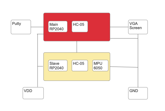
Figure 1: High Level Block Diagram
Logical Structure
Figure 1 presents an overview of our project. It consists of the main Pico RP2040 that is connected with the master HC-05 bluetooth module, Putty for serial communication and the VGA screen. The second block consists of another Pico RP2040 that is connected to the slave HC-05 bluetooth module and a MPU6050 sensor.
We created a wireless controller that is used to interact with a menu which is displayed on the VGA screen. A player first sets a reference point by pointing towards the screen and press confirm, this helps setting a reference point for movement calculations. Then the player uses the motion controller to move the cursor by pointing directly at the VGA screen and moving the controller. The player can then select the start game menu item to begin the tic tac toe game. The other menu items displayed do not have any functionality, but if the group had more time the player could also choose between single player and multiplayer as well as change the settings for the game. The player can then start by making the first move of the game. After the player has made its move, the game will toggle players and the other player takes the controller and places his move. Using this cursor and inputting a command to Putty, the players can select which box to place its character in.
The controller is only able to sense movement from the IMU and is directly communicating with the main PICO which handles the logic for computing where to display the cursor, given the positional information from the controller PICOs. The main pico also handles the game logic, meaning deciding whose turn it is, displaying the board and deciding the winner. Communication between the controller and the main PICO is done by transferring data with the use of bluetooth modules. The bluetooth protocol follows a master-slave implementation. As such, the master PICO is the PICO directly responsible for the outputs. The slave is the controller which would like to connect to the main PICO and is the one processing measurements from the IMU.
Background Math
The MPU6050 plays a pivotal role in this project. It is a combined 6-degree of freedom (DoF) sensor that integrates a 3-axis gyroscope and a 3-axis accelerometer. However, in this particular implementation, the focus is primarily on the gyroscope component for motion tracking. The gyroscope in the MPU6050 is a MEMS (Micro-Electro-Mechanical Systems) gyroscope. Meaning that it operates based on the Coriolis Effect.
This effect is a fundamental principle in physics that explains how the movement of a vibrating mass is influenced when it is subjected to rotational motion. Here’s a detailed look into how this works and its implications in the context of gyroscopes.
The Coriolis Effect describes how a moving object appears to follow a curved path when observed from a rotating frame of reference. In the case of gyroscopes in MEMS devices, a tiny mass is made to vibrate along a straight path. When the device is rotated, the path of this mass appears to deviate due to the Coriolis force. In our gyroscope, a mass is set into oscillation. When the gyroscope rotates, the Coriolis force acts on the vibrating mass, causing it to move perpendicular to both its direction of vibration and the axis of rotation. This perpendicular movement is detected by capacitive sensors within the MEMS structure, which then convert it into an electrical signal. The intensity of this signal is proportional to the rate of rotation.
The cross product yields a vector perpendicular to both the velocity of the vibrating mass and the rotation axis, indicating the direction of the Coriolis force.
The math regarding the gyroscope is straightforward. As noted, it directly measures rotation rate. So, if we know the initial angle for our system (𝜃o) and our sample rate (1/Δ𝑡)), we can use the gyroscope to integrate that angle for all time.
The advantage is that gyroscopes are less noisy than accelerometers in the short term. They provide smoother and more stable readings for small, quick movements. For this project, this means that the cursor movements on the VGA display will be fluid and responsive to small, quick motions of the controller. This allows players to make precise selections on the VGA screen with minimal latency or overshoot, enhancing the gameplay experience.
However, over time, gyroscopes tend to drift, leading to accumulated errors in angle estimation. This phenomenon, known as gyro drift, is significant in applications requiring precise and long-term angle measurements.The process we are using, where gyro measurements are integrated over time to estimate the angle, while it's effective in the short term, it inherently accumulates errors over time. This manifests in our project as a slow deviation of the cursor from its intended path, especially noticeable during prolonged usage. In our project, when the controller remains stationary for extended periods, or if the sensor is used continuously over a long duration, this drift could result in the cursor gradually moving or not holding its position accurately.
The gyroscopic data is ideal for the real-time control required in the project, where quick, short movements translate directly to cursor movement on the screen. However, the long-term drift of the gyroscope means that for extended play sessions or if the controller is left idle, the cursor might slowly drift away from its intended position. This necessitates occasional recalibration or resetting of the controller's position to ensure continued accuracy during gameplay.
The MPU6050 measures the force to determine the angular velocity around its three axes (x, y, z). In our code, we are specifically interested in the x-axis (gyro[2]) and the y-axis(gyro[0]), which we scale to obtain a measure of horizontal movement (dx) and vertical movement (dy). The scaling factor adjusts the sensitivity of the cursor movement.
Movement calculations are determined by gyroscopic movement (process_gyro_data_for_x) and (process_gyro_data_for_y). The gyroscope's axis data is scaled to derive the horizontal and vertical movement. This represents how much the device has rotated about the x-axis, corresponding to lateral movement and linear acceleration along the y-axis, corresponding to up and down movement.
Our clamp movement function prevents excessively large movements by setting a maximum limit (max_movement). If the calculated movement exceeds this limit, it is clamped to this maximum value. This avoids sudden large jumps of the cursor on the screen and helps with the user experience.
We then use these calculations to map it to the VGA screen(map_to_screen_coordinates). The relative movements (dx, dy) are scaled according to screen dimensions to map them to screen coordinates (screen_x, screen_y). This mapping ensures that the sensor's movements correspond accurately to movements on the screen. Scaling factors for x and y axes (x_scale, y_scale) are used to control the sensitivity of this mapping. We also have a function that ensures that the resulting screen coordinates do not go off-screen.
The data gathering (getData) function checks if the device is calibrated so we know it's set to a known position which is used as a reference. If calibrated, it reads the current orientation from the MPU6050 and calculates the relative movement, which is then mapped to screen coordinates.
This project leverages the gyroscope data from the MPU6050 to create a motion-controlled interface. The mathematical processing of this data is key, enabling the translation of physical rotations (detected by the MPU6050) into digital cursor movements on a screen with precision and smoothness. This approach focuses solely on gyroscopic data, setting aside accelerometer inputs.
Hardware/Software Tradeoffs
Since our project focused on displaying real time sensor measurements on a screen, our goal was to make the software as fast as possible and the hardware fairly simple. That's the reason we chose a VGA screen, which is a cost-effective solution. However, it limits the resolution and color depth compared to more modern display technologies like HDMI. Secondly, MPU6050 sensor combines both accelerometer and gyroscope, p
Technologies used
Hardware components
- RP2040
- VGA display
- IMU
- MPU6050
- gyroscope
- accelerometer
- Bluetooth module
Software & tools
- C
- Arduino IDE
Project demo video
What you get
- Working project / hardware kit, tested before delivery
- Complete source code with explanation
- Project demo and guidance for your viva
- Project report, PPT and IEEE paper support (on request)
Related Embedded Systems projects

Gas Leakage Detector Using Arduino
A budget-friendly LPG gas leak detector built with an Arduino and MQ-5 gas sensor, triggering a buzzer and LED when unsafe gas levels are de...
View project
Simple Alarm System
A beginner-friendly home alarm with PIR motion sensing, keypad PIN entry, and separate entry/exit timing delays, built to be easy to expand.
View project
Ultrasonic Sensor Project with Arduino UNO Q
A beginner-friendly first Arduino UNO Q project: a servo-swept ultrasonic sensor that renders a live sweeping radar display in a web browser...
View project
3D Audio Localization
[Fall 2025] We designed a real-time embedded system that localizes sound sources in three dimensions and visualizes them live using a four-m...
View project