SpectroTuner
[Fall 2025] We built an adjustable spectrogram and tuner because we wanted to be able to (for lack of better words) tune the pitch as well as the tone of an instrument. We thought that it would be possible to do this by showing the frequency spectrum of the instrument over time, while also allowing for traditional instrument tuning through a graphical interface.
- Suitable forB.Tech/B.E Embedded Systems students
- Build time4-6 weeks
- LevelBeginner
- Available atAjvika Labs, Kakinada
About this project
Authors:
Date:
December 19, 2025
Course:
ECE 4760
1. Project Introduction
The Sound Bite
"An adjustable spectrogram that is also a tuner… Or maybe, an adjustable tuner that is also a spectrogram?"
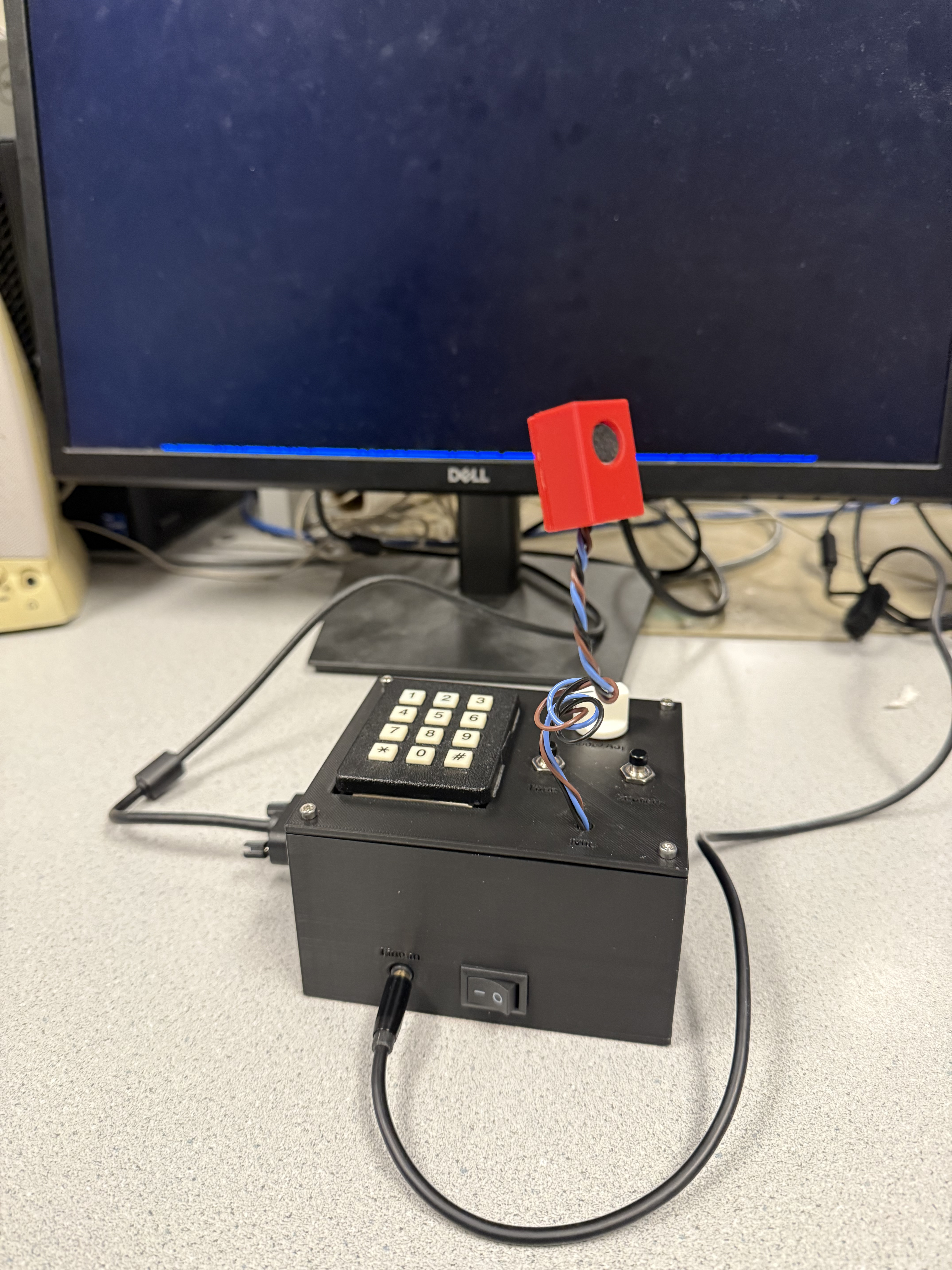
Fig.1 - The finished spectrotuner
Summary
We built an adjustable spectrogram and tuner because we wanted to be able to (for lack of better words) tune the pitch as well as the tone of an instrument. We thought that it would be possible to do this by showing the frequency spectrum of the instrument over time, while also allowing for traditional instrument tuning through a graphical interface.
2. High Level Design
Rationale and Sources
We thought it would be interesting to build a device that allows musicians to tune their instruments while also
seeing a visualization of how their actions (changing effects, techniques, voicings, etc.) affect their tone.
While there is not much immediate utility exposed through this, since music is for the ears, we expect that allowing
artists another way to interpret their sound while configuring the media they perform through could spark creativity
and encourage a deeper understanding of why things sound the way they do. This is because seeing a real-time spectral
representation of one's sound makes it easy to see the patterns and shifts in harmonics as they change various parameters.
Background Math
On a high level, our project relies on two different mathematical processes: a Discrete-Time Fourier Transform and a
Fundamental Frequency Recognition process. The essential functions of our project are a spectrogram and a visual
tuning function that pulls data from the spectrogram to ascertain what note is coming from an input source. Both
the spectrogram and tuner are highly adjustable, with the spectrogram allowing for variation of draw speed and input
sensitivity, and the tuner allowing for variation of tuning reference (e.g. A = 440 Hz), as well as octave and note.
The mathematical nature of the Fourier transform will be discussed in later sections, since the discrete code implementation
does not immediately conceptualize a Fourier transform.
We perform a Discrete-Time Fourier Transform on the input from either the microphone or the line-in, which serves
to provide us with information about the relative strengths of frequencies present in one time-step of the input.
We use this information for plotting and tuning. The way that our tuning code works involves selecting the most
prominent frequency in a time-step of the Fourier transform and checking if it is inside of a pre-computed 40-cent
bounding box around the frequency dictated by the user's note choice. A cent is a musical unit, defined as one-hundredth
of the frequency difference between two notes. The computation of the bounding boxes involves logarithms, since the
human perception of audio is logarithmic with respect to pitch. This also means that musical notes get further apart
in frequency in higher octaves, so our tuning indicators make larger jumps in frequency as higher octaves are selected for tuning.
Logical Structure
Fig.2 - Hardware Diagram
The logical structure of our project consists of four main blocks: sound input, signal processing, visualization, and
parameter modification. The sound input is converted into a frequency mapping by the signal processing block, which
is visualized according to user-selected parameters that are set by the parameter modification block. Each of these
blocks consist of one or more threads running on the microcontroller.
Hardware/Software Tradeoffs
Some of the hardware trade offs we made in our design include worse part quality, since our ordered parts from Digikey
did not arrive in time, and we needed to integrate the hardware to do final testing. Because of this, we settled for
some lower quality hardware from the lab, including a cheaper microphone module than what we initially planned, that
in theory would be slightly less well-suited for our application. We did not really have to make any major software
trade offs, since the Raspberry Pi Pico's software tooling and Protothreads library allowed us to create all the
functionality that we needed.
Existing IP
Our project does not appear to infringe upon any patents, copyrights, or trademarks.
3. Program/Hardware Design
Program Details
a. FFT/Spectrogram
The mathematically-heaviest part of our code is contained within the FFT protothread, which reads from the ADC using DMA, and uses this information as the source for an in-place FFT. The Cooley-Tukey FFT algorithm we used is the same as is included in the FFT demo in the ECE 4760 RP2040 Demos repository. The Cooley-Tukey algorithm works to reduce the computation required to calculate Discrete-Time Fourier Transforms by a massive amount (O(n2) vs. O(nlogn)) by breaking the operation into smaller and smaller groups of calculations, until only pairs of data points remain. Then, the algorithm leverages the symmetry inherent in Fourier Transforms to quickly calculate the magnitudes of each pair, before recombining every point back together to produce an array containing the transformed input. This implementation is also done in fixed-point arithmetic, which is generally much faster than floating point on the RP2040, since it doesn't have a dedicated FPU. The post-fft samples are then used to get the relative strengths of each frequency. The source of the FFT is determined by the source mode, which allows for different channels of the ADC to be read so that input can come from either the microphone or the line-in. The ADC FIFO is cleared before the FFT runs on a new source so that data corruption/false outputs do not happen. We primarily relied upon the RP2040 VGA driver provided earlier in the course for displaying to the VGA, but we did have to write our own code to allow the PIO state machines to function properly when the RP2040 was running at higher clock speeds. We pushed it to 250 MHz.
Fig.3 - Work in progress image of the spectrogram on the VGA display
b. Inlined Functions
Fig.4 - Inlined Functions High Level Diagram.
There are three inline functions that we implemented: freq_2_spectro(), read_encoder_terminals(), and update_tuning_params().
We implemented freq_2_spectro() to convert the fix15 frequency inputted to the function to a proportional y-value that will
be displayed on the spectrogram. The implementation is essentially the inverse way of how the FFT puts the magnitudes into bins.
In the FFT thread, each vertical time slice is drawn from the top down and the y-value that correlates to a bin of the FFT is
retained within the for loop as variable i. In freq_2_spectro(), we compute the “i” or y-value with y = (SPECTRO_HEIGHT - 1) -
(fix2int15(bin) << 1) which is the reverse of the FFT implementation. The value is then clamped to the lower and upper bounds
of the spectrogram and returned.
As for read_encoder_terminals(), implementing a rotary encoder given the library we found was quite simple compared to attempting
to use the potentiometer. We used this function to get a four bit packet, 0xBA, which held the encoded value of the two pins of
the rotary encoder. We first store the two values of the corresponding GPIO pins, convert them to the inverted version since the
signals are active low with pull-ups, and then return (a | ( b << 1)) & 0x3, which recovers 0xBA from the GPIO values A and B.
This function is then used when determining if the rotary encoder is spun clockwise or counterclockwise.
The last inline function update_tuning_params() allows us to reset the tuning bounds and reset the graph easily throughout the program.
To calculate the tuning bounds, we first get the base note that the user wants to tune to and then grab the desired octave to tune to.
The function then recalculates the tuning note based on the octave ((base note * 2^(octave - 4)), we subtract 4 since the base note
is in the fourth octave) and the center frequency by multiplying the note frequency at the desired octave by the ratio of the center
frequency over 440Hz (correlates to the standard tuning reference frequency). This resulting tuning frequency is used to calculate
the upper (multiplied by the cents_padding) and lower (divided by the cents_padding) bounds of the tuning frequency.
The cents_padding depends on the number of cents, which is calculated by taking 2^(cents/1200). Typically, good tuning is based on
+/-10 cents around the desired frequency, but to make the tuning more accessible for the average person's vocals and for the bounds to
show up better on the display, we used +/-40 cents.
While testing the spectrogram, we noticed that the drawn tuning bounds would often overlap when displayed. This is mostly due to FFT
frequency resolution and integer rounding when converting the calculated frequencies to pixel coordinates. A 20 to 40Hz cent offset
around the notes is typically around the order of a few Hz (for C4, 261.63Hz with bounds of +/-20 cents the range is 6.04Hz), while
the bin spacing (Fs/NUM_SAMP
Technologies used
Hardware components
- RP2040
- Raspberry Pi Pico
- VGA display
- microphone
- ADC
Software & tools
- C
- Arduino IDE
Project demo video
What you get
- Working project / hardware kit, tested before delivery
- Complete source code with explanation
- Project demo and guidance for your viva
- Project report, PPT and IEEE paper support (on request)
Related Embedded Systems projects

Gas Leakage Detector Using Arduino
A budget-friendly LPG gas leak detector built with an Arduino and MQ-5 gas sensor, triggering a buzzer and LED when unsafe gas levels are de...
View project
Simple Alarm System
A beginner-friendly home alarm with PIR motion sensing, keypad PIN entry, and separate entry/exit timing delays, built to be easy to expand.
View project
Ultrasonic Sensor Project with Arduino UNO Q
A beginner-friendly first Arduino UNO Q project: a servo-swept ultrasonic sensor that renders a live sweeping radar display in a web browser...
View project
3D Audio Localization
[Fall 2025] We designed a real-time embedded system that localizes sound sources in three dimensions and visualizes them live using a four-m...
View project