Spatial audio murder mystery
[Fall 2022] By using the Raspberry Pi Pico, this project implements spatial audio into a fun and interactive murder mystery game. We generated self-recorded audio and passed it to headphones while applying a spatial audio algorithm to the input audio. To the headphone user, the audio appears to be coming from the specific direction the user chooses with the joystick. The goal is to closely mimic how sounds in real life reach our ears, depending on where the sound is coming from.
- Suitable forB.Tech/B.E Embedded Systems students
- Build time4-6 weeks
- LevelBeginner
- Available atAjvika Labs, Kakinada
About this project
Spatial Audio Murder Mystery
Introduction
High Level
Hardware
Software
Results
Conclusions
References
Appendices
Spatial Audio Murder Mystery
ECE4760 Project
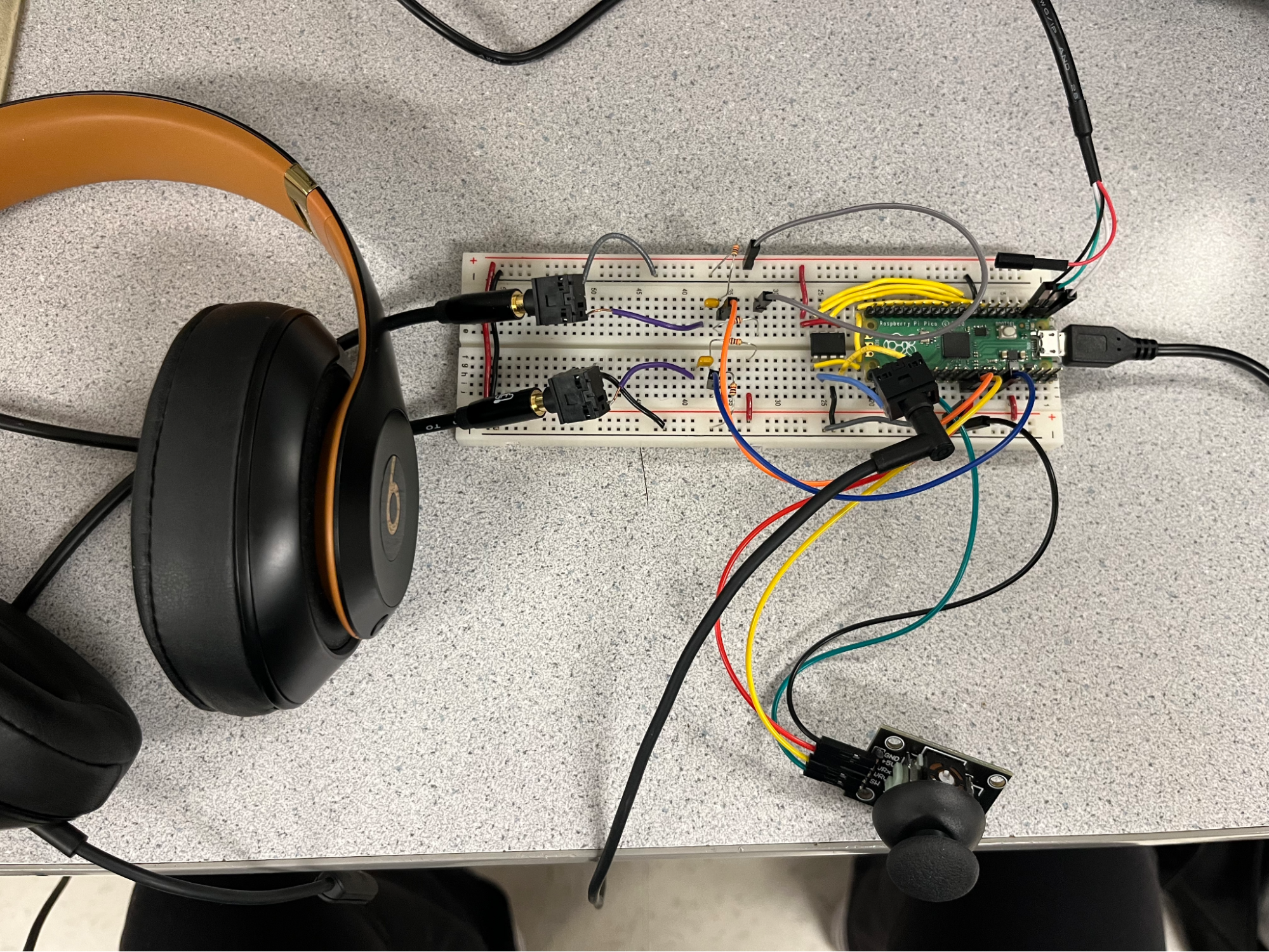
Fig.1 Full hardware setup of the murder mystery
Introduction
By using the Raspberry Pi Pico, this project implements spatial audio into a fun and interactive murder mystery game. We generated self-recorded audio and passed it to headphones while applying a spatial audio algorithm to the input audio. To the headphone user, the audio appears to be coming from the specific direction the user chooses with the joystick. The goal is to closely mimic how sounds in real life reach our ears, depending on where the sound is coming from.
High Level Design
Spatial Audio
Spatial audio simulates sound localization, the ability to detect where a sound is coming from and how far it is, to “trick” the human brain when listening to input audio. For example, spatial audio would make you think someone is speaking to you front-on or someone is speaking to your left even if you are alone and not moving. The human brain is very good at detecting where a sound is coming from and here, we artificially created this effect using spatial audio. Basic versions of spatial audio is already a feature that many tech companies use. For example, when listening to the song “Left and Right” by Charlie Puth through Apple headphones, you would be able to hear the music as if it is solely coming from your left or your right.
We thought this would be a cool final project idea because of the increasing innovation in headphones and audio technology. Therefore, being able to build a simple version of spatial audio would be a good introduction to some of the more complex algorithms that are being developed today. Because some of the past projects in this class also implemented spatial audio, we wanted to not just simply implement spatial audio but also use it as a main component to a game. In the audio game, sound/voices would come from the 5 directions illustrated below.
Fig.2 5 directions game audio can come from
Game Design
The game is single-player murder mystery game that has no visuals and is solely dependent on audio. Set in a spacious mansion, the game involves 3 rooms and 6 characters: Mr. Hopper(Head of the house), Ethan(Brother), Clara(Sister), Liz(Maid), Francis(Gardener), and Sydney(Cook). The victim is Mrs. Hopper(Mr. Hopper’s wife). The game begins with a short introduction that briefly explains the game structure. This introduction specifies the spatial audio nature of the game and encourages the player to use the joystick to choose who to focus on and who to have in the background. The joystick is important because each of the 3 rooms contains 2 of the 6 characters, each speaking their side of the story. If the player does not choose one of the 2 players to focus on, they will only be able to hear muffled voices coming from both. Figure 3 below shows how the player will perceive the direction of both voices when they use the joystick to choose a specific voice.
Fig.3 How joystick changes the game’s audio direction
At the end of the game, the player must make a guess on who the murderer is. Because there are 3 rooms, the player can only focus on 3 voices per game. This means that the player is only exposed to 3 individual stories per game. Thus there are 2^3 ways the player can hear the stories, giving each player a unique playing experience.
Basic Structure
This is a general overview of the structure of the project. A detailed description of each part, both hardware and software, are described in the “Hardware”, “Software”, and “Results” sections below.
Sound, analog data, is outputted to the headphones via a headphone jack, yet the algorithms that make the input audio into the desired spatial audio is done with software and therefore with digital data. This means that a Digital-to-Analog converter is necessary. We used the DAC circuit and output audio jack circuit we built in Lab1 for the cricket synthesis as the general purpose of the circuit remained the same: to transform digital output from the Pico to analog input that can be heard when a speaker/headphones is plugged into the audio jack.
Because we wanted to focus on the spatial audio algorithm, we began the project with no input audio to the Pico. Rather, we synthesized beeps by using direct digital synthesis similar to how we created beeps in lab 1. We tested our algorithm with the beeps and this helped us gain a better understanding of how the algorithm works and how we can manipulate the algorithm so that the beeps are coming from the desired angle.
We first began user interaction with the audio by using UART transmission so that the user could type in the desired direction, illustrated above as #0-#4, on PuTTY. This was only done because the joystick we ordered did not arrive yet. This transmission and receival of data between the two devices (lab computer and Raspberry Pi Pico) was done through the two dataline that exist on the UART channel. The connection between the two devices were done by using a USB type A plug breakout cable with female jumpers. The connection to the lab computer was done by simple plugging in the USB type A end. As shown in the block diagram below in the “Hardware” section, the connection to the Raspberry Pi Pico was done by connecting the Tx wire, which receives data from the computer to GPIO 0 (pin 1), the Rx wire, which transmits data to the computer, to GPIO 1, and the ground wire to GND (pin 3). The power wire was not connected to anything as it was not needed.
The joystick was then used to control the direction of the output audio. The Pico would read the x and y positions from the joystick and if both were within a certain range then it would mean the user has chosen 1 of the 5 directions.
The game audio was inputted through two audio jacks (because two people are talking at the same time) that were connected to a simple voltage-level shifter circuit. This voltage level shifter circuit was necessary because we needed to adjust for the voltage range of the Pico’s ADC inputs (0 to 3.3V). We had two input audios, one character talking for the left ear (controlled by core 0) and one character for the right ear (controlled by core 1). Both audios used Pico’s ADC pins, ADC 0 and ADC 1 respectively. The ADC pins were necessary because the input audio was analog data but the Pico does the spatial audio algorithm on digital data.
The joystick needs two ADC pins and the game input audio also needs two ADC pins, but the Pico only has 3 ADC pins! We decided to let the joystick only use one ADC pin, so the joystick was limited to the x direction.
Throughout the entire process of completing this project, we tested each step with the oscilloscope, speakers, and headphones. The oscilloscope would tell us if our output audio was indeed behaving correctly, as in whether we were observing spatial audio behavior. The speaker and headphones were used to see if the output audio actually sounded like it was coming from the desired direction. To negate bias, we frequently asked Professor Hunter Adams to wear headphones and guess the direction of the audio.
Background Math
The spatial audio algorithm we implemented is a simplified head-related transfer function (HRTF). An input audio becomes spatial audio when the audio that goes to each is slightly different in regards to time and amplitude. The time difference is known as the interaural time difference (ITD) and the amplitude difference is known as the interaural level difference (ILD). For example, if we want to mimic a sound coming from the left of a person, then the audio to the left ear would remain unchanged while the audio to the right ear would be delayed and with a lower amplitude. The ITD and ILD can be calculated by first assuming the top of the human head as a sphere and that both ears are exactly opposite of each other. This is so that the sound direction can be radial (Figure 4).
Fig.4 simplified head-related transfer function
Fig.5 5 directions game audio can come from
For simplicity, we used the same calculations for ITD and ILD as in the 2021 and 2015 projects (linked in References). In the formula, a is the head radius and c is the speed of sound. As shown in Figure 5, we chose 5 directions: θ=-π/3 -π/4, 0, π/3, and π/4 radians. For each of the directions, we calculate the ITD and ILD and use the results to manipulate the corresponding input audio. Additionally, ITD was also multiplied by 40,000 cycles per second (time between each ISR call) to represent delays in cycles. This was because the spatial audio algorithm was all done in the ISR for each core. For all 5 directions, ITD and ILD were calculated by hand so that the Pico did not need to do any calculations. The results for all 5 directions are listed below:
Direction #0 and #4: ITD = 20; ILD = 0.5
Direction #1 and #3: ITD = 16; ILD = 0.7
Direction #2: ITD = 0; ILD = 1
Note that these results were also slightly adjusted based on user experience. Say if direction 1 were chosen, then the audio to the right ear (governed by core 1) would remain unchanged in time and amplitude and the audio to the left ear would be delayed by ITD and its amplitude would be decreased by ILD. For a better user experience in the game we made both audios quieter by dividing the audio by a small number to decrease the voltage.
Hardware/Software Tradeoffs
Because we wanted spatial audio to be present in both ears, the two input audios needed to be summed together and output into the DAC in both interrupt service routines. The Pico’s processing speed could not slow down as both cores needed to do spatial audio algorithms on their respective input audio and send it to both ears at the same time. This meant that we needed to be careful about how the audio is inputted. We discussed the idea of using a microphone to pick up the audio a
Technologies used
Hardware components
- Raspberry Pi Pico
- IMU
- microphone
- speaker
- DAC
- ADC
Software & tools
- C
- Arduino IDE
Project demo video
What you get
- Working project / hardware kit, tested before delivery
- Complete source code with explanation
- Project demo and guidance for your viva
- Project report, PPT and IEEE paper support (on request)
Related Embedded Systems projects

Gas Leakage Detector Using Arduino
A budget-friendly LPG gas leak detector built with an Arduino and MQ-5 gas sensor, triggering a buzzer and LED when unsafe gas levels are de...
View project
Simple Alarm System
A beginner-friendly home alarm with PIR motion sensing, keypad PIN entry, and separate entry/exit timing delays, built to be easy to expand.
View project
Ultrasonic Sensor Project with Arduino UNO Q
A beginner-friendly first Arduino UNO Q project: a servo-swept ultrasonic sensor that renders a live sweeping radar display in a web browser...
View project
3D Audio Localization
[Fall 2025] We designed a real-time embedded system that localizes sound sources in three dimensions and visualizes them live using a four-m...
View project