Spatial audio hat
Spring 2025 ECE 4750 Final ProjectBy Anishka Raina (ar933), Arnav Shah (aks274), Yoon Kang (dk844)May 16, 2025
- Suitable forB.Tech/B.E Embedded Systems students
- Build time4-6 weeks
- LevelBeginner
- Available atAjvika Labs, Kakinada
About this project
Toggle navigation
Spatial Audio Hat
Introduction
High Level Design
Hardware
Software
Testing
Results
Conclusion
References
Appendices
Spatial Audio Hat
Spring 2025 ECE 4750 Final Project
May 16, 2025
Figure 1: Full setup of project
Introduction
We designed a head-mounted device that helps users perceive the direction and proximity of nearby objects using spatial audio cues. The system uses a TF-Luna LiDAR sensor for real-time distance measurement and a potentiometer to estimate head orientation. A Raspberry Pi Pico processes this data and generates directional audio using direct digital synthesis (DDS), output through a DAC and stereo audio jack. When the user presses a button to initiate a scan, the device identifies the closest obstacle and plays a tone that is louder in either the left or right ear to simulate direction, while pitch represents proximity. Our goal was to build a low-cost, embedded spatial perception system that could one day assist individuals with visual impairments.
High Level Design
Project Idea
The motivation for this project came from our interest in designing assistive technology that allows users to interact with their environment more intuitively. Spatial audio, already widely used in commercial technology like airpods, seemed like a good way for us to give real-time feedback in a wearable form. We were particularly interested in how we could combine multiple peripherals (UART for LiDAR communication, ADC for reading analog input from the potentiometer, SPI for audio output, and real-time computation) on a resource constrained platform like the Raspberry Pi Pico.
While some past projects have implemented spatial audio, our approach stands out by integrating live object detection using LiDAR rather than using pre-recorded audio cues. This makes our system fully reactive to the user's environment. The spatial audio adjusts the amplitude and timing to simulate directionality, allowing users to identify object locations solely through sound and without need for visual input.
Background Math
ITD measures the difference in the arrival time of a sound between both ears. If sound arrives from the left for example, the sound will take less time to propagate and reach the left ear compared to the time to reach the right ear. Our brains are able to pick up on this slight time delay which is on the order of tens to hundreds of microseconds. We can calculate this time delay using basic math where the time delay as a function of theta is given by the following: ITD(theta) = d/c * sin(theta), where d and c are constants corresponding to the distance between one’s ears and the speed of sound (343 m/s). In our project, we assume the distance between the ears is 18 cm. The angle theta corresponds to the offset from some reference point, which we initially take to be the direction corresponding to the 0 for the potentiometer.
Figure 2: Interaural Time Difference Drawing
To compute the angle values for the potentiometer, which is an analog sensor, we measured the raw ADC values from 0 to 4095 and then mapped that to an angle between 0 and 180 degrees (corresponding to head position) after clamping.
Logical Structure
From the user’s perspective, they are required to ensure that they click the button to proceed to the next state in our FSM and also that the arrow on the potentiometer lines up with the direction their head is facing. There are four main states in our FSM. After the last button press, the system resets back to the initial state.
Once the user has mounted the hat and is holding the breadboard with the potentiometer, they can click the button to start the system. We begin in the INIT state. After the first button press, the system enters the SCAN state. Here, the user should remain stationary and rotate their head from 0 to 180 degrees, while ensuring the potentiometer direction lines up with their actual head direction. During this scan, the system collects LiDAR readings in 5-degree increments and records the angle of the closest object.
After the scan, the system transitions to the AUDIO DIRECTION state. In this state, the system uses interaural time differences to create the illusion that the tone is coming from the direction of the closest object. As the user turns their head, the perceived audio source changes, allowing them to identify where the object is using only sound cues.
After another button press, the user enters the AUDIO PROXIMITY state. In this state, the tone's frequency varies depending on how close the user is to the object. The beeps occur more frequently as the user gets closer, and less frequently as they move away, serving as a proximity alert. A final button press resets the system to the INIT state.
The user hears the beeps through headphones plugged into a stereo jack, which receives analog output from the DAC. The tones themselves are generated using Direct Digital Synthesis (DDS), allowing for flexible frequency and stereo control.
Copyrights
To our knowledge, our project does not infringe on any patents or trademarks. We used open-source libraries and sample code provided in this course's curriculum, specifically the DDS and DAC example from Lab 1. This code was modified to support stereo output and spatial audio behavior. The TF-Luna LiDAR and potentiometer were purchased from Adafruit and are based on components with publicly available datasheets and specifications.
Hardware Design
Figure 3: Complete High Level Hardware Schematic
We have 6 main parts in the hardware design of our project, as seen in the figure 3 above. It is the Raspberry Pi Pico, the DAC, the audio jack, the potentiometer, a button, and the TF-Luna LiDAR. The DAC, audio jack, potentiometer, and button were all parts we used in previous labs. However, the TF-Luna LiDAR was chosen for the purpose of finding the distance from the nearest object and our system. We decided on this specific edition since it could see up to 175 cm and was cheap and small enough to mount on our hat. In addition, we powered the system using a separate battery pack mounted on the hat, rather than relying on the Pico's USB connection, since the system must be mobile.
Our spatial audio perception system's hardware is divided into two main components: a hat-mounted unit for sensing and audio output, and a handheld controller for user input. This design allows for intuitive interaction while maintaining the core sensing and feedback mechanisms in a wearable format.
The heart of our system is the Raspberry Pi Pico microcontroller, which we mounted on a breadboard attached to a flat hat. The Pico's dual-core processor handles our real-time audio synthesis and sensor data processing needs efficiently. We utilized several of the Pico's GPIO pins for various functions: pins 8 and 9 for UART communication with the LiDAR, pins 10, 11, and 13 for SPI interface with the DAC, pin 28 for analog input from the potentiometer, and pin 14 for the pushbutton input.
Hat-Mounted Unit
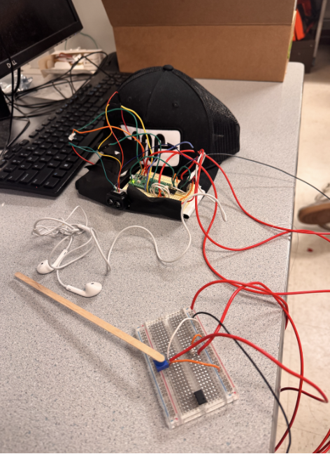
On the hat, alongside the Pico, we mounted the TF-Luna LiDAR sensor. We positioned this compact distance measurement tool at the front of the cap, ensuring an unobstructed view for accurate object detection. The LiDAR connects to the Pico via UART, allowing for rapid, precise distance measurements crucial for our application. Also on the hat-mounted breadboard, we placed the dual-channel DAC and stereo audio jack, forming the core of our audio output system. This setup generates independent left and right audio channels, essential for creating the spatial audio effects that convey directional information to the user. The audio jack, connected to the DAC outputs, allows users to plug in standard headphones for an immersive audio experience. The system that was mounted on the hat can be seen below in figure 4.
Figure 4: Hardware mounted on hat
Handheld Controller
The second major component of our hardware setup is the handheld controller. This consists of a separate breadboard housing a potentiometer and a pushbutton. The potentiometer, connected to the Pico's ADC input via a flexible wire, allows users to simulate head rotation by adjusting the "direction" they are facing. We mapped the potentiometer's position to angles between 0° and 180°, providing an intuitive way to test directional audio feedback without the complexity of actual head tracking at this stage of development. The pushbutton on the handheld unit enables users to cycle through different modes of operation, such as room scanning, directional audio feedback, and proximity-based audio cues. We implemented software debouncing in our main control loop to ensure reliable button presses and state changes. The system that acted as the handheld controller can be seen in figure 5 below.
Figure 5: Hardware for user control
Challenges & Future Improvements
Throughout the development process, we encountered several challenges. Balancing the weight distribution on the hat required careful placement of components, especially after adding the battery pack. We also had to ensure that the wires connecting the handheld unit to the hat-mounted system were long enough for comfortable use but not so long as to become unwieldy. This was something we had trouble customizing, as everyone has different heights. In the end, we had to just make the wires extremely long, thus not being able to make it as compact as we wanted. There were some initial audio quality issues, where noise was experienced. In addition, the headphones we used had a microphone attached to it, so we could not insert it all the way. However, these were addressed through careful grounding techniques and component placement on the hat-mounted breadboard.
Looking ahead, we've identified several areas for hardware improvement. If we were able to do this project for an entire semester, transitioning to a custom PCB design for both the hat-mounted unit and the handheld controll
Spatial Audio Hat
Introduction
High Level Design
Hardware
Software
Testing
Results
Conclusion
References
Appendices
Spatial Audio Hat
Spring 2025 ECE 4750 Final Project
May 16, 2025
Figure 1: Full setup of project
Introduction
We designed a head-mounted device that helps users perceive the direction and proximity of nearby objects using spatial audio cues. The system uses a TF-Luna LiDAR sensor for real-time distance measurement and a potentiometer to estimate head orientation. A Raspberry Pi Pico processes this data and generates directional audio using direct digital synthesis (DDS), output through a DAC and stereo audio jack. When the user presses a button to initiate a scan, the device identifies the closest obstacle and plays a tone that is louder in either the left or right ear to simulate direction, while pitch represents proximity. Our goal was to build a low-cost, embedded spatial perception system that could one day assist individuals with visual impairments.
High Level Design
Project Idea
The motivation for this project came from our interest in designing assistive technology that allows users to interact with their environment more intuitively. Spatial audio, already widely used in commercial technology like airpods, seemed like a good way for us to give real-time feedback in a wearable form. We were particularly interested in how we could combine multiple peripherals (UART for LiDAR communication, ADC for reading analog input from the potentiometer, SPI for audio output, and real-time computation) on a resource constrained platform like the Raspberry Pi Pico.
While some past projects have implemented spatial audio, our approach stands out by integrating live object detection using LiDAR rather than using pre-recorded audio cues. This makes our system fully reactive to the user's environment. The spatial audio adjusts the amplitude and timing to simulate directionality, allowing users to identify object locations solely through sound and without need for visual input.
Background Math
ITD measures the difference in the arrival time of a sound between both ears. If sound arrives from the left for example, the sound will take less time to propagate and reach the left ear compared to the time to reach the right ear. Our brains are able to pick up on this slight time delay which is on the order of tens to hundreds of microseconds. We can calculate this time delay using basic math where the time delay as a function of theta is given by the following: ITD(theta) = d/c * sin(theta), where d and c are constants corresponding to the distance between one’s ears and the speed of sound (343 m/s). In our project, we assume the distance between the ears is 18 cm. The angle theta corresponds to the offset from some reference point, which we initially take to be the direction corresponding to the 0 for the potentiometer.
Figure 2: Interaural Time Difference Drawing
To compute the angle values for the potentiometer, which is an analog sensor, we measured the raw ADC values from 0 to 4095 and then mapped that to an angle between 0 and 180 degrees (corresponding to head position) after clamping.
Logical Structure
From the user’s perspective, they are required to ensure that they click the button to proceed to the next state in our FSM and also that the arrow on the potentiometer lines up with the direction their head is facing. There are four main states in our FSM. After the last button press, the system resets back to the initial state.
Once the user has mounted the hat and is holding the breadboard with the potentiometer, they can click the button to start the system. We begin in the INIT state. After the first button press, the system enters the SCAN state. Here, the user should remain stationary and rotate their head from 0 to 180 degrees, while ensuring the potentiometer direction lines up with their actual head direction. During this scan, the system collects LiDAR readings in 5-degree increments and records the angle of the closest object.
After the scan, the system transitions to the AUDIO DIRECTION state. In this state, the system uses interaural time differences to create the illusion that the tone is coming from the direction of the closest object. As the user turns their head, the perceived audio source changes, allowing them to identify where the object is using only sound cues.
After another button press, the user enters the AUDIO PROXIMITY state. In this state, the tone's frequency varies depending on how close the user is to the object. The beeps occur more frequently as the user gets closer, and less frequently as they move away, serving as a proximity alert. A final button press resets the system to the INIT state.
The user hears the beeps through headphones plugged into a stereo jack, which receives analog output from the DAC. The tones themselves are generated using Direct Digital Synthesis (DDS), allowing for flexible frequency and stereo control.
Copyrights
To our knowledge, our project does not infringe on any patents or trademarks. We used open-source libraries and sample code provided in this course's curriculum, specifically the DDS and DAC example from Lab 1. This code was modified to support stereo output and spatial audio behavior. The TF-Luna LiDAR and potentiometer were purchased from Adafruit and are based on components with publicly available datasheets and specifications.
Hardware Design
Figure 3: Complete High Level Hardware Schematic
We have 6 main parts in the hardware design of our project, as seen in the figure 3 above. It is the Raspberry Pi Pico, the DAC, the audio jack, the potentiometer, a button, and the TF-Luna LiDAR. The DAC, audio jack, potentiometer, and button were all parts we used in previous labs. However, the TF-Luna LiDAR was chosen for the purpose of finding the distance from the nearest object and our system. We decided on this specific edition since it could see up to 175 cm and was cheap and small enough to mount on our hat. In addition, we powered the system using a separate battery pack mounted on the hat, rather than relying on the Pico's USB connection, since the system must be mobile.
Our spatial audio perception system's hardware is divided into two main components: a hat-mounted unit for sensing and audio output, and a handheld controller for user input. This design allows for intuitive interaction while maintaining the core sensing and feedback mechanisms in a wearable format.
The heart of our system is the Raspberry Pi Pico microcontroller, which we mounted on a breadboard attached to a flat hat. The Pico's dual-core processor handles our real-time audio synthesis and sensor data processing needs efficiently. We utilized several of the Pico's GPIO pins for various functions: pins 8 and 9 for UART communication with the LiDAR, pins 10, 11, and 13 for SPI interface with the DAC, pin 28 for analog input from the potentiometer, and pin 14 for the pushbutton input.
Hat-Mounted Unit
On the hat, alongside the Pico, we mounted the TF-Luna LiDAR sensor. We positioned this compact distance measurement tool at the front of the cap, ensuring an unobstructed view for accurate object detection. The LiDAR connects to the Pico via UART, allowing for rapid, precise distance measurements crucial for our application. Also on the hat-mounted breadboard, we placed the dual-channel DAC and stereo audio jack, forming the core of our audio output system. This setup generates independent left and right audio channels, essential for creating the spatial audio effects that convey directional information to the user. The audio jack, connected to the DAC outputs, allows users to plug in standard headphones for an immersive audio experience. The system that was mounted on the hat can be seen below in figure 4.
Figure 4: Hardware mounted on hat
Handheld Controller
The second major component of our hardware setup is the handheld controller. This consists of a separate breadboard housing a potentiometer and a pushbutton. The potentiometer, connected to the Pico's ADC input via a flexible wire, allows users to simulate head rotation by adjusting the "direction" they are facing. We mapped the potentiometer's position to angles between 0° and 180°, providing an intuitive way to test directional audio feedback without the complexity of actual head tracking at this stage of development. The pushbutton on the handheld unit enables users to cycle through different modes of operation, such as room scanning, directional audio feedback, and proximity-based audio cues. We implemented software debouncing in our main control loop to ensure reliable button presses and state changes. The system that acted as the handheld controller can be seen in figure 5 below.
Figure 5: Hardware for user control
Challenges & Future Improvements
Throughout the development process, we encountered several challenges. Balancing the weight distribution on the hat required careful placement of components, especially after adding the battery pack. We also had to ensure that the wires connecting the handheld unit to the hat-mounted system were long enough for comfortable use but not so long as to become unwieldy. This was something we had trouble customizing, as everyone has different heights. In the end, we had to just make the wires extremely long, thus not being able to make it as compact as we wanted. There were some initial audio quality issues, where noise was experienced. In addition, the headphones we used had a microphone attached to it, so we could not insert it all the way. However, these were addressed through careful grounding techniques and component placement on the hat-mounted breadboard.
Looking ahead, we've identified several areas for hardware improvement. If we were able to do this project for an entire semester, transitioning to a custom PCB design for both the hat-mounted unit and the handheld controll
Technologies used
Hardware components
- Raspberry Pi Pico
- IMU
- microphone
- DAC
- ADC
Software & tools
- C
- Arduino IDE
Project demo video
What you get
- Working project / hardware kit, tested before delivery
- Complete source code with explanation
- Project demo and guidance for your viva
- Project report, PPT and IEEE paper support (on request)
Delivery & Payment
Delivery takes a minimum of two weeks from the date your inquiry is confirmed.
Payment is in two parts:
• 50% advance to start the project
• Remaining 50% before delivery
Note:
• Documentation and PPT are not included by default
• If you need documentation/PPT, it can be arranged for extra time and cost
We'll confirm the exact timeline and cost with you after reviewing your requirements.
Related Embedded Systems projects

Embedded Systems
Gas Leakage Detector Using Arduino
A budget-friendly LPG gas leak detector built with an Arduino and MQ-5 gas sensor, triggering a buzzer and LED when unsafe gas levels are de...
View project
Embedded Systems
Simple Alarm System
A beginner-friendly home alarm with PIR motion sensing, keypad PIN entry, and separate entry/exit timing delays, built to be easy to expand.
View project
Embedded Systems
Ultrasonic Sensor Project with Arduino UNO Q
A beginner-friendly first Arduino UNO Q project: a servo-swept ultrasonic sensor that renders a live sweeping radar display in a web browser...
View project
Embedded Systems
3D Audio Localization
[Fall 2025] We designed a real-time embedded system that localizes sound sources in three dimensions and visualizes them live using a four-m...
View project