Sisyphys-inspired sand drawing table
[Spring 2025] Infinite loops? We call that a featureA Project By Aidan Derocher, Jorge Corpa Chung, Henry Calderon
- Suitable forB.Tech/B.E Embedded Systems students
- Build time4-6 weeks
- LevelAdvanced
- Available atAjvika Labs, Kakinada
About this project
Toggle navigation
Sand Table
Introduction
Project Objective
Design
Result
Conclusion
Sisyphus-inspired sand drawing table
Infinite loops? We call that a feature
A Project By Aidan Derocher, Jorge Corpa Chung, Henry Calderon
Demonstration Video
Introduction
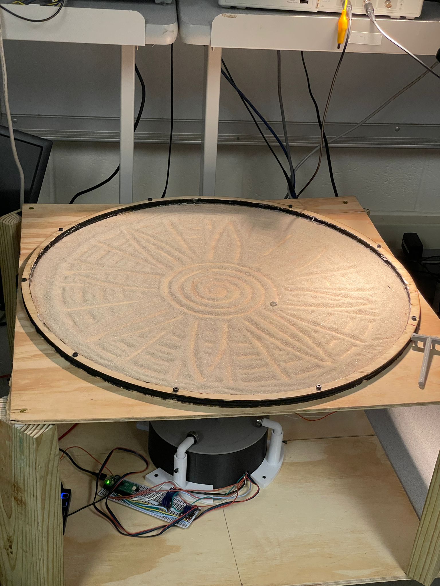
This project explores the design and fabrication of a Sisyphus-inspired sand drawing table, a kinetic sculpture that creates intricate patterns by dragging a steel ball through sand using a magnetic system beneath the surface.
The table operates on a polar coordinate gantry system, a rototating arm beneath the table with a motorized gantry that slides along its length.
This system is powered by two stepper motors and controlled through a Raspberry Pi Pico, enabling the steel ball to draw complex geometric patterns in fine sand.
Project Objective:
Design and build a functional Sisyphus sand drawing table using a polar coordinate gantry system
Implement precise motor control using stepper motors and TMC2209 drivers
Design and fabricate custom components via 3D printing and laser cutting.
Explore pattern generation algorithms, including circular, spiral, and heart shaped patterns
Design
Hardware Design
As part of the hardware design process, there were many meetings being held in front of a white board since none of the team members had any background in mechanical engineering.
These sessions were essential to break down the challenges step by step and arrive at workable solutions.
For the hardware design, the system was built around two motors: one responsible for rotating the beam that supports the gantry, and the other for driving the gantry itself using a belt mechanism wrapped around the second motor.
The entire setup was mounted beneath a wooden table, allowing the metal ball on top to be manipulated via magnets fixed to the gantry.
This concept was partially inspired by a magnetic sand table designed by Roberto Groza.
The hardware section was divided into three main components: The wooden table, the rotating base supporting the beam, and the gantry system on the beam.
The table construction was left till last, as its height and dimensions were determined by the rest of the assembly.
This ensured the magnet beneath the surface would be positioned just millimeters from the table to maximize its magnetic influence on the metal ball above the table.
The overall circuit design ran off of two separate power sources. The RPI Pico is run off of a 5V microusb port, and powered each of the TMC2209 motor controllers
off of the 3.3 volt rail. An external power supply was used in order to actually power the Nema17 motors. These motors are specified for 12 amps to 24 amps and
1.5 maximum amps. Through experimentation, we found these motors could actually be underamped to 6 volts, but would end up drawing significantly more current. For
our final demonstration, we ended up running off of 20 volts as this would only draw 0.8 amps consistently. The three components that would end up spinning, being one
motor and two buttons, ended running up through the slip ring such that the wires would not tangle while the table is spinning. Each button had a pull down resistor
and were active high. Each motor driver has 4 GPIO pins connecting to them. These connect to a microstep 1 and 2 port, which is used to select how many microsteps the driver
would take per full step. Each motor driver also had a step pin, which when it recieved a pulse, would make the motor turn one step. Finally, the motors had a direction
pin, which would drive clockwise when pulled low and counterclockwise when pulled high. Each of these boards took both the 3.3V power and 20V power as inputs, and had 4
outputs total motor drive outputs.
The gantry system consisted of several custom 3D-printed parts, including a motor mount that secures to the beam, a moving gantry cart driven by the belt, and a return mount at the opposite end to loop the belt back.
Multiple iterations of each component were required to fine-tune their dimensions, particularly the height and spacing, so the belt could run smoothly with minimal friction during motion.
After the design was settled, buttons were added onto each side of the mount at the end of the beam so the motor could calibrate the steps required to move the gantry from one end to the other.
This was implemented to ensure the gantry cart would not slide off the end of the beam and collide with the mounts.
One of the biggest challenges in this project was creating the system to spin the metal bar. This was one of the most critical systems as it
needed to hold the full weight of the aluminum bar and the attached motor while wobbling as little as possible while spinning. Additionally,
since wires needed to be ran to the motor driving the gantry and each of the end switch buttons, the wires needed to not tangle while the base
spun. The initial idea for accomplishing this was to create a way to directly affix the motor to the bar. However, this was scrapped quite
quickly as it provided no way for the wires to not tangle. The next idea was to instead use a spur gear to spin a vertical rod that had the bar
attached on top. Then, a slip ring could be used to run the wires down the center of the spinning mechanism, ideally preventing them from getting tangled.
This was implemented by 3D printing a piece that could attach to the T-slot bar via M5 screws, screwing in tight to it. The slip ring then slotted in to
the bottom of this piece, and another 3d printed part would clamp it in place. This second part could then be fit on top of a rod with bearings on it to
spin freely. This can be seen below:
While this design did spin and attach to the bar firmly, due to being attached to the base only via one rod,
it wobbled quite a lot, meaning that it would make for shaky patterns. Thus, we decided to redesign this base mechanism to be more stable.
This was done by making the base far larger by making it function as a rotary table. Instead of the earlier spur gear design, a plate
that was sitting on top of bearings was spun using a planetary gear. By having a much larger base and more points of contact, this design was much
more stable. The cad for this redesign is shown below, as well as the assembly:
However, this redesign still had a flaw, as nothing was holding the top of the container down. This meant that depending on the gantry position, it
would lift off the top of the container. To solve this, additional mounts were added to use bearings to clamp the top down. These would mount
into the base board and screw in to hold the top down. This resulted in a stable base that was able to spin consistently smooth.
After testing the system a few times, it was clear that the beam was still unstable.
The problem stems from the 3D printed material between the shaft and the rotary table whad too little infill to support the spinning beam.
The proper way to solve the issue would have been to reprint the shaft to have stronger support as it did to hold the beam up.
However, that would have taken too much time so it was decided that the gear printed on the shaft could be used as the top of a support and rectangular structures could be tight fit in between.
By elevating the heavier side with the motor, the magnet height would become even resulting in more consistant results.
Another problem that came up was that the space for the slip ring was too tight, causing the wires to get caught on the side wall and get twisted as the beam spins.
Additionally, some of the wires started behaving faulty, specifically for the buttons. This meant that the whole setup needed to be removed and wires were resoldered as some got snapped.
To solve this issue, the first thing that was done was to apply heatshrink on top of all the wires together to ensure it could not get twisted.
The second step taken to ensure that the wires had more space so they could spin freely, which was accomplished by widening the channel they were run through. When the connections were
resoldered, each of the connections were tested with a multimeter to ensure consistent connectivity and no shorts. With all of this troubleshooting completed, we
ran some more comprehensive system tests such as running the base contiguously for an extended period of time to ensure that the wires were not getting twisted. Additionally, the
behavior of the gantry and buttons was verified, and it was all tested together, validating each component.
The actual table itself is constructed of 1/4 inch wood as the surface for the sand to be on, using 2 by 4s as legs for the table. The total
dimensions came out to be 605mm by 605mm by 330mm. By building the table as a square, it gave just enough clearance for the 640mm bar to spin underneath without collision.
The base board for the table was made of 1/2 inch wood to screw mount everything on. A ring of diameter 595mm was laser cut out of 1/2 inch wood in order to keep the sand within the
table throughout the trials. In order to ensure that the gantry wouldn't drag on the bottom of the table, we additionally printed out spacers to allow us to adjust the
height of the table by a few millimeters at a time.
Software Design
The software fo
Sand Table
Introduction
Project Objective
Design
Result
Conclusion
Sisyphus-inspired sand drawing table
Infinite loops? We call that a feature
A Project By Aidan Derocher, Jorge Corpa Chung, Henry Calderon
Demonstration Video
Introduction
This project explores the design and fabrication of a Sisyphus-inspired sand drawing table, a kinetic sculpture that creates intricate patterns by dragging a steel ball through sand using a magnetic system beneath the surface.
The table operates on a polar coordinate gantry system, a rototating arm beneath the table with a motorized gantry that slides along its length.
This system is powered by two stepper motors and controlled through a Raspberry Pi Pico, enabling the steel ball to draw complex geometric patterns in fine sand.
Project Objective:
Design and build a functional Sisyphus sand drawing table using a polar coordinate gantry system
Implement precise motor control using stepper motors and TMC2209 drivers
Design and fabricate custom components via 3D printing and laser cutting.
Explore pattern generation algorithms, including circular, spiral, and heart shaped patterns
Design
Hardware Design
As part of the hardware design process, there were many meetings being held in front of a white board since none of the team members had any background in mechanical engineering.
These sessions were essential to break down the challenges step by step and arrive at workable solutions.
For the hardware design, the system was built around two motors: one responsible for rotating the beam that supports the gantry, and the other for driving the gantry itself using a belt mechanism wrapped around the second motor.
The entire setup was mounted beneath a wooden table, allowing the metal ball on top to be manipulated via magnets fixed to the gantry.
This concept was partially inspired by a magnetic sand table designed by Roberto Groza.
The hardware section was divided into three main components: The wooden table, the rotating base supporting the beam, and the gantry system on the beam.
The table construction was left till last, as its height and dimensions were determined by the rest of the assembly.
This ensured the magnet beneath the surface would be positioned just millimeters from the table to maximize its magnetic influence on the metal ball above the table.
The overall circuit design ran off of two separate power sources. The RPI Pico is run off of a 5V microusb port, and powered each of the TMC2209 motor controllers
off of the 3.3 volt rail. An external power supply was used in order to actually power the Nema17 motors. These motors are specified for 12 amps to 24 amps and
1.5 maximum amps. Through experimentation, we found these motors could actually be underamped to 6 volts, but would end up drawing significantly more current. For
our final demonstration, we ended up running off of 20 volts as this would only draw 0.8 amps consistently. The three components that would end up spinning, being one
motor and two buttons, ended running up through the slip ring such that the wires would not tangle while the table is spinning. Each button had a pull down resistor
and were active high. Each motor driver has 4 GPIO pins connecting to them. These connect to a microstep 1 and 2 port, which is used to select how many microsteps the driver
would take per full step. Each motor driver also had a step pin, which when it recieved a pulse, would make the motor turn one step. Finally, the motors had a direction
pin, which would drive clockwise when pulled low and counterclockwise when pulled high. Each of these boards took both the 3.3V power and 20V power as inputs, and had 4
outputs total motor drive outputs.
The gantry system consisted of several custom 3D-printed parts, including a motor mount that secures to the beam, a moving gantry cart driven by the belt, and a return mount at the opposite end to loop the belt back.
Multiple iterations of each component were required to fine-tune their dimensions, particularly the height and spacing, so the belt could run smoothly with minimal friction during motion.
After the design was settled, buttons were added onto each side of the mount at the end of the beam so the motor could calibrate the steps required to move the gantry from one end to the other.
This was implemented to ensure the gantry cart would not slide off the end of the beam and collide with the mounts.
One of the biggest challenges in this project was creating the system to spin the metal bar. This was one of the most critical systems as it
needed to hold the full weight of the aluminum bar and the attached motor while wobbling as little as possible while spinning. Additionally,
since wires needed to be ran to the motor driving the gantry and each of the end switch buttons, the wires needed to not tangle while the base
spun. The initial idea for accomplishing this was to create a way to directly affix the motor to the bar. However, this was scrapped quite
quickly as it provided no way for the wires to not tangle. The next idea was to instead use a spur gear to spin a vertical rod that had the bar
attached on top. Then, a slip ring could be used to run the wires down the center of the spinning mechanism, ideally preventing them from getting tangled.
This was implemented by 3D printing a piece that could attach to the T-slot bar via M5 screws, screwing in tight to it. The slip ring then slotted in to
the bottom of this piece, and another 3d printed part would clamp it in place. This second part could then be fit on top of a rod with bearings on it to
spin freely. This can be seen below:
While this design did spin and attach to the bar firmly, due to being attached to the base only via one rod,
it wobbled quite a lot, meaning that it would make for shaky patterns. Thus, we decided to redesign this base mechanism to be more stable.
This was done by making the base far larger by making it function as a rotary table. Instead of the earlier spur gear design, a plate
that was sitting on top of bearings was spun using a planetary gear. By having a much larger base and more points of contact, this design was much
more stable. The cad for this redesign is shown below, as well as the assembly:
However, this redesign still had a flaw, as nothing was holding the top of the container down. This meant that depending on the gantry position, it
would lift off the top of the container. To solve this, additional mounts were added to use bearings to clamp the top down. These would mount
into the base board and screw in to hold the top down. This resulted in a stable base that was able to spin consistently smooth.
After testing the system a few times, it was clear that the beam was still unstable.
The problem stems from the 3D printed material between the shaft and the rotary table whad too little infill to support the spinning beam.
The proper way to solve the issue would have been to reprint the shaft to have stronger support as it did to hold the beam up.
However, that would have taken too much time so it was decided that the gear printed on the shaft could be used as the top of a support and rectangular structures could be tight fit in between.
By elevating the heavier side with the motor, the magnet height would become even resulting in more consistant results.
Another problem that came up was that the space for the slip ring was too tight, causing the wires to get caught on the side wall and get twisted as the beam spins.
Additionally, some of the wires started behaving faulty, specifically for the buttons. This meant that the whole setup needed to be removed and wires were resoldered as some got snapped.
To solve this issue, the first thing that was done was to apply heatshrink on top of all the wires together to ensure it could not get twisted.
The second step taken to ensure that the wires had more space so they could spin freely, which was accomplished by widening the channel they were run through. When the connections were
resoldered, each of the connections were tested with a multimeter to ensure consistent connectivity and no shorts. With all of this troubleshooting completed, we
ran some more comprehensive system tests such as running the base contiguously for an extended period of time to ensure that the wires were not getting twisted. Additionally, the
behavior of the gantry and buttons was verified, and it was all tested together, validating each component.
The actual table itself is constructed of 1/4 inch wood as the surface for the sand to be on, using 2 by 4s as legs for the table. The total
dimensions came out to be 605mm by 605mm by 330mm. By building the table as a square, it gave just enough clearance for the 640mm bar to spin underneath without collision.
The base board for the table was made of 1/2 inch wood to screw mount everything on. A ring of diameter 595mm was laser cut out of 1/2 inch wood in order to keep the sand within the
table throughout the trials. In order to ensure that the gantry wouldn't drag on the bottom of the table, we additionally printed out spacers to allow us to adjust the
height of the table by a few millimeters at a time.
Software Design
The software fo
Technologies used
Hardware components
- Raspberry Pi Pico
- stepper motor
- IMU
- motor driver
Software & tools
- C
- Arduino IDE
Project demo video
What you get
- Working project / hardware kit, tested before delivery
- Complete source code with explanation
- Project demo and guidance for your viva
- Project report, PPT and IEEE paper support (on request)
Delivery & Payment
Delivery takes a minimum of two weeks from the date your inquiry is confirmed.
Payment is in two parts:
• 50% advance to start the project
• Remaining 50% before delivery
Note:
• Documentation and PPT are not included by default
• If you need documentation/PPT, it can be arranged for extra time and cost
We'll confirm the exact timeline and cost with you after reviewing your requirements.
Related Embedded Systems projects

Embedded Systems
Gas Leakage Detector Using Arduino
A budget-friendly LPG gas leak detector built with an Arduino and MQ-5 gas sensor, triggering a buzzer and LED when unsafe gas levels are de...
View project
Embedded Systems
Simple Alarm System
A beginner-friendly home alarm with PIR motion sensing, keypad PIN entry, and separate entry/exit timing delays, built to be easy to expand.
View project
Embedded Systems
Ultrasonic Sensor Project with Arduino UNO Q
A beginner-friendly first Arduino UNO Q project: a servo-swept ultrasonic sensor that renders a live sweeping radar display in a web browser...
View project
Embedded Systems
3D Audio Localization
[Fall 2025] We designed a real-time embedded system that localizes sound sources in three dimensions and visualizes them live using a four-m...
View project