Simulated mini golf
[Spring 2025] Cornell University -- ECE 4760 -- Digital Systems Design Using MicrocontrollersA Project By Henry Geller, Robert Haig, and Daniel WahabMay 2025
- Suitable forB.Tech/B.E Embedded Systems students
- Build time4-6 weeks
- LevelBeginner
- Available atAjvika Labs, Kakinada
About this project
Toggle navigation
Mini Golf Game
Introduction
Gameplay
High-Level Design
Software
Hardware
Results
Conclusions
Simulating Mini Golf Using the Raspberry Pi Pico
Cornell University -- ECE 4760 -- Digital Systems Design Using Microcontrollers
A Project By Henry Geller, Robert Haig, and Daniel Wahab
May 2025
This project is a mini golf video game where the controller is an actual golf putter.
Introduction
In the long history of sports video games, golf has carved its own lane. In 2006, the wildly popular Wii Sports game included golf as one of its five sports, which centered around the use of the Wii remote as if it were a golf club. In 2016, Apple launched GamePigeon along with the release of iOS 10, where one of its most popular games was mini golf. The development of golf video games occurred in parallel with the development of golf simulators, which are meant to replicate the experience of playing golf on a real golf course as closely as possible. When using a golf simulator, the player swings real clubs and hits a real ball, the path of the ball is sensed using technology, and then a virtual ball moves through a virtual course on a large projector screen. These simulators are used as an avenue for serious golfers to improve their game when real courses are unavailable or unaffordable. The goal of this project was to combine Wii Golf, GamePigeon mini golf, and a golf simulator into a golf game where a real putter is used to direct the motion of a golf ball in a virtual mini golf course.
Gameplay
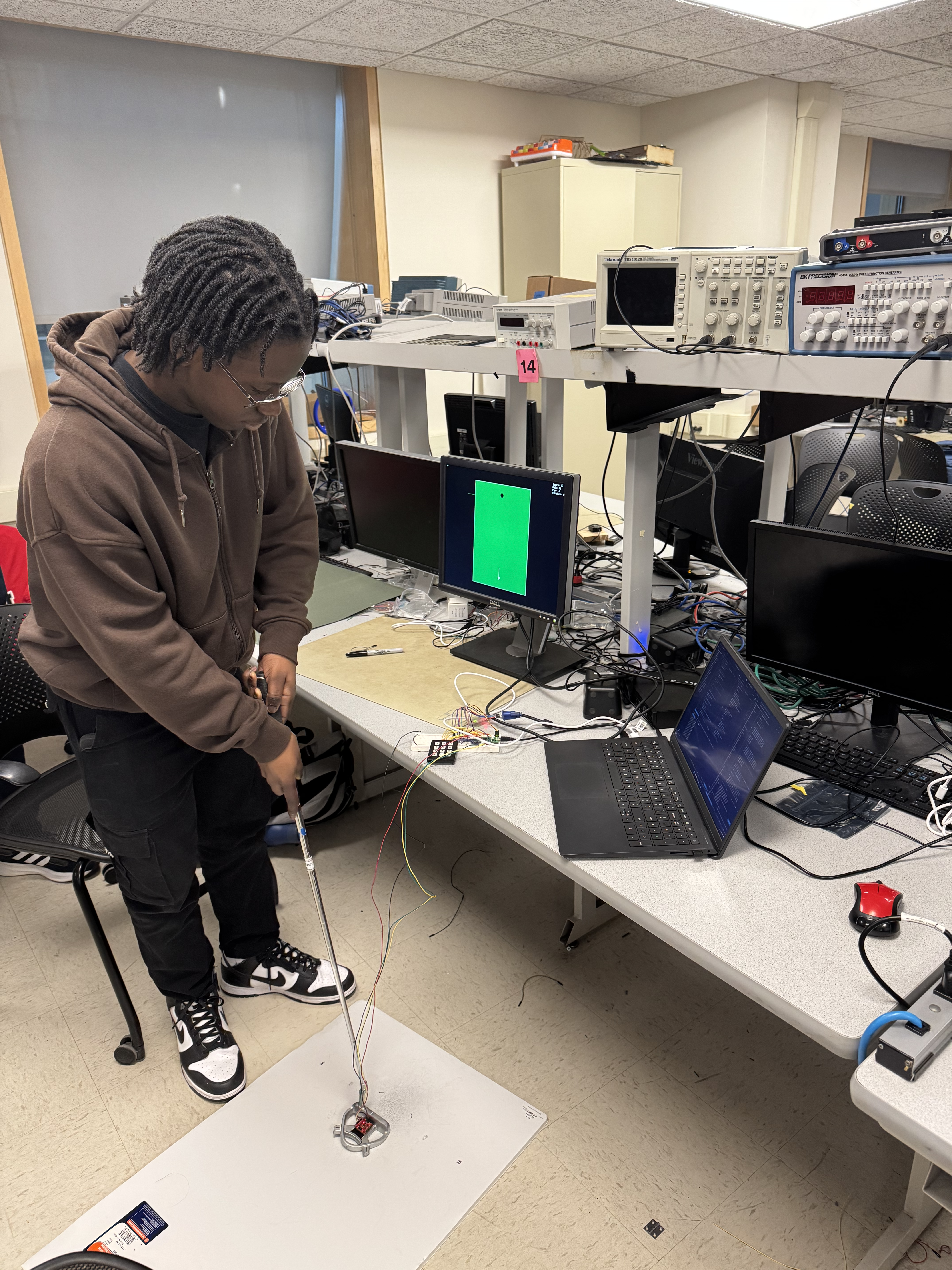
Image 1: An action shot of Dan playing the game. He starts with the putter between the magnets and swings in the direction of the VGA screen.
The player can begin playing the game by turning on the Pico. The first screen is a view of the first hole. All holes in the game are shown from a bird's eye view, as if there were a camera stationed above a mini golf hole pointing down. The ball is shown in its starting position. Protruding from the ball is a line which we call the heading vector, which indicates the direction that the ball will go if the putter is swung from its current position. As the player holds the putter above the floor mat containing carefully arranged magnets, the player can change the direction of the heading vector by angling the putter, as if changing the direction they intended to hit a real ball sitting on the mat. So that the player does not need to turn around and face away from the screen, the '9' key can be pressed on the keypad in order to rotate the heading vector by 90 degrees. Once the player has lined up their shot, they can swing the putter as they normally would to hit a golf ball, with a back swing followed by a front swing and a follow through. Based on the speed of the putter and the orientation of the club, the ball will move on the screen in a physically realistic manner, slowing down over time and bouncing off the boundaries of the green. In the upper right corner of the screen, there is a continuous display of the player's score for the hole and the round.
Image 2: The scoreboard at the top of the screen indicating that the user has taken four shots on hole 1 which is a par 3.
Each hole is assigned a par, and the score relative to par after each hole is what affects the score for the round. Once the ball goes in the hole, then the next hole begins immediately. The game consists of four holes. At the end of the final hole, there is a screen which says 'Game Over' and reports the player's final score relative to par. At any time, including at the 'Game Over' screen, the player can restart the game by pressing '1' on the keypad.
High-Level Design
The centerpiece of the system running this game is the Raspberry Pi Pico, which contains an RP2040 microcontroller. The Pico is powered by a laptop via a USB connection, and it controls three different peripheral devices: a VGA screen, an inertial measurement unit (IMU), and a keypad.
Figure 1: A high-level hardware diagram of the project. The Pico connects to three peripheral devices: the keypad, the VGA screen, and the IMU. The magnets at the top are read by the magnetometer.
The RP2040 supplies the VGA screen with the five signals it needs to operate: horizontal sync, vertical sync, red, green, and blue. These signals are created and timed using a VGA driver written in assembly for the Programmable I/O module of the RP2040 by our professor Hunter Adams [1].
The IMU is a 9-axis IMU, which means it can read acceleration, angular velocity, and magnetic field in 3 axes each [2]. It is attached to the club head of the putter, and it reports information about the club's orientation and speed to the RP2040, so that the ball can move accordingly. The putter we use is a Tour Edge Reaction 3 putter.
Image 3: The IMU resting on top of the putter.
The keypad is a simple 12-key keypad that allows the user to enter any number 0-11, although only numbers 1 and 9 are used in this game. The code which probes the keypad for any pressed keys was also written by Hunter Adams [3].
On the software side, there are three threads running on the RP2040, with each being responsible for interacting with one of the peripheral devices.
Software
Keypad
The simplest of the three threads is the thread responsible for sensing the pressing of keys on the keypad. The code for this came directly from the demo code provided by Professor Adams with little modification.
When using a mechanical button, there is concern that one press of the button may be detected as multiple distinct presses, due to the spring inside the button that may cause it to oscillate for some time. To help prevent this, we require a button press to be detected multiple times in succession before officially declaring that a press has been detected. Therefore, rather than watching for a rising or falling edge of a signal and recording a button press each time, there is a finite state machine that is used to verify a button press.
Figure 2: Debouncing state machine for keypad presses.
The keypad thread contains a while loop that runs continuously as long as the system is operational. Each time through the while loop, a check of all the buttons is performed to detect if any buttons are currently pressed down. This check must show the same button being pressed on two consecutive iterations of the while loop in order for that button press to officially be declared. Similarly, when a button is let go, the lack of a button press must be detected for two consecutive iterations in order for the press to be considered over. This behavior is enforced by the use of an FSM which contains four states: NOT_PRESSED, MAYBE_PRESSED, PRESSED, and MAYBE_NOT_PRESSED. The point at which a press has been officially detected is during the state transition from MAYBE_PRESSED to PRESSED, and the point at which a press is officially over is during the state transition from MAYBE_NOT_PRESSED to NOT_PRESSED, although the end of a press never has any effect on the game.
There are only two buttons on the keypad that have any effect on the game. If the '1' button is pressed at any time during the game, the game is reset to its initial state, when there is no score at the beginning of the first hole. If the '9' button is pressed, then the heading vector protruding from the ball is rotated 90 degrees clockwise, to make it easier for the player to hit the ball in any direction they would like. The heading vector is updated regardless of whether it is shown on the screen at the time.
IMU
The ability to interface with the IMU was its own software problem that needed to be solved. We decided that for our purposes the IMU values only needed to be read at a rate of 100 Hz, or every 0.01 seconds. To achieve this, we utilized the hardware system timer on the RP2040, and used it to generate an interrupt every 0.01 seconds. This interrupt triggers an interrupt service routine (ISR) which reads data from all 9 axes of the IMU using the function
icm20948_read_raw()
. This data includes the acceleration data that is used to detect swings and swing speed, as well as the magnetometer data that is used to calculate heading. The last thing the ISR does is signal the thread that is associated with the IMU.
In addition to the ISR, there is a thread dedicated to the IMU which contains a while loop that is always running. However, at the top of the loop body, there is a direction for the thread to wait until it has received the signal from the ISR to continue running. The effect of this is that the body of the while loop runs once each time the ISR is called. We expect that the code would have had the same functionality if the body of the loop had been contained within the ISR itself.
The responsibility of the rest of the loop body is to record swings of the putter based on the IMU data. A swing of the putter is detected via a progression through a finite state machine.
Figure 3: Swing detection state machine.
State transitions are triggered by sequences of acceleration values along the x-axis, which points in the direction that the ball would move if the club hit a real ball. The system begins in the IDLE state, which means that no swing is currently taking place. The program has a need for the heading of the club, both for the displaying of a heading vector and for the movement of the ball after a swing. Since there is an inherent amount of noise in the magnetometer readings, the heading angle that is used is always an average of the previous 20 readings, which are captured over a period of 0.2 seconds. In the IDLE state, the only action that is taken is to remove the oldest value from a FIFO queue of heading readings, and to replace it with the newest value. Then, the average of the 20 headings is re-calculated and used by the animation thread to display the heading vector in the proper place.
A backswing is sensed when there has been 15 consecutive acceleration readings of at least -1.5, which is a condition that was chosen via experimentation. In t
Mini Golf Game
Introduction
Gameplay
High-Level Design
Software
Hardware
Results
Conclusions
Simulating Mini Golf Using the Raspberry Pi Pico
Cornell University -- ECE 4760 -- Digital Systems Design Using Microcontrollers
A Project By Henry Geller, Robert Haig, and Daniel Wahab
May 2025
This project is a mini golf video game where the controller is an actual golf putter.
Introduction
In the long history of sports video games, golf has carved its own lane. In 2006, the wildly popular Wii Sports game included golf as one of its five sports, which centered around the use of the Wii remote as if it were a golf club. In 2016, Apple launched GamePigeon along with the release of iOS 10, where one of its most popular games was mini golf. The development of golf video games occurred in parallel with the development of golf simulators, which are meant to replicate the experience of playing golf on a real golf course as closely as possible. When using a golf simulator, the player swings real clubs and hits a real ball, the path of the ball is sensed using technology, and then a virtual ball moves through a virtual course on a large projector screen. These simulators are used as an avenue for serious golfers to improve their game when real courses are unavailable or unaffordable. The goal of this project was to combine Wii Golf, GamePigeon mini golf, and a golf simulator into a golf game where a real putter is used to direct the motion of a golf ball in a virtual mini golf course.
Gameplay
Image 1: An action shot of Dan playing the game. He starts with the putter between the magnets and swings in the direction of the VGA screen.
The player can begin playing the game by turning on the Pico. The first screen is a view of the first hole. All holes in the game are shown from a bird's eye view, as if there were a camera stationed above a mini golf hole pointing down. The ball is shown in its starting position. Protruding from the ball is a line which we call the heading vector, which indicates the direction that the ball will go if the putter is swung from its current position. As the player holds the putter above the floor mat containing carefully arranged magnets, the player can change the direction of the heading vector by angling the putter, as if changing the direction they intended to hit a real ball sitting on the mat. So that the player does not need to turn around and face away from the screen, the '9' key can be pressed on the keypad in order to rotate the heading vector by 90 degrees. Once the player has lined up their shot, they can swing the putter as they normally would to hit a golf ball, with a back swing followed by a front swing and a follow through. Based on the speed of the putter and the orientation of the club, the ball will move on the screen in a physically realistic manner, slowing down over time and bouncing off the boundaries of the green. In the upper right corner of the screen, there is a continuous display of the player's score for the hole and the round.
Image 2: The scoreboard at the top of the screen indicating that the user has taken four shots on hole 1 which is a par 3.
Each hole is assigned a par, and the score relative to par after each hole is what affects the score for the round. Once the ball goes in the hole, then the next hole begins immediately. The game consists of four holes. At the end of the final hole, there is a screen which says 'Game Over' and reports the player's final score relative to par. At any time, including at the 'Game Over' screen, the player can restart the game by pressing '1' on the keypad.
High-Level Design
The centerpiece of the system running this game is the Raspberry Pi Pico, which contains an RP2040 microcontroller. The Pico is powered by a laptop via a USB connection, and it controls three different peripheral devices: a VGA screen, an inertial measurement unit (IMU), and a keypad.
Figure 1: A high-level hardware diagram of the project. The Pico connects to three peripheral devices: the keypad, the VGA screen, and the IMU. The magnets at the top are read by the magnetometer.
The RP2040 supplies the VGA screen with the five signals it needs to operate: horizontal sync, vertical sync, red, green, and blue. These signals are created and timed using a VGA driver written in assembly for the Programmable I/O module of the RP2040 by our professor Hunter Adams [1].
The IMU is a 9-axis IMU, which means it can read acceleration, angular velocity, and magnetic field in 3 axes each [2]. It is attached to the club head of the putter, and it reports information about the club's orientation and speed to the RP2040, so that the ball can move accordingly. The putter we use is a Tour Edge Reaction 3 putter.
Image 3: The IMU resting on top of the putter.
The keypad is a simple 12-key keypad that allows the user to enter any number 0-11, although only numbers 1 and 9 are used in this game. The code which probes the keypad for any pressed keys was also written by Hunter Adams [3].
On the software side, there are three threads running on the RP2040, with each being responsible for interacting with one of the peripheral devices.
Software
Keypad
The simplest of the three threads is the thread responsible for sensing the pressing of keys on the keypad. The code for this came directly from the demo code provided by Professor Adams with little modification.
When using a mechanical button, there is concern that one press of the button may be detected as multiple distinct presses, due to the spring inside the button that may cause it to oscillate for some time. To help prevent this, we require a button press to be detected multiple times in succession before officially declaring that a press has been detected. Therefore, rather than watching for a rising or falling edge of a signal and recording a button press each time, there is a finite state machine that is used to verify a button press.
Figure 2: Debouncing state machine for keypad presses.
The keypad thread contains a while loop that runs continuously as long as the system is operational. Each time through the while loop, a check of all the buttons is performed to detect if any buttons are currently pressed down. This check must show the same button being pressed on two consecutive iterations of the while loop in order for that button press to officially be declared. Similarly, when a button is let go, the lack of a button press must be detected for two consecutive iterations in order for the press to be considered over. This behavior is enforced by the use of an FSM which contains four states: NOT_PRESSED, MAYBE_PRESSED, PRESSED, and MAYBE_NOT_PRESSED. The point at which a press has been officially detected is during the state transition from MAYBE_PRESSED to PRESSED, and the point at which a press is officially over is during the state transition from MAYBE_NOT_PRESSED to NOT_PRESSED, although the end of a press never has any effect on the game.
There are only two buttons on the keypad that have any effect on the game. If the '1' button is pressed at any time during the game, the game is reset to its initial state, when there is no score at the beginning of the first hole. If the '9' button is pressed, then the heading vector protruding from the ball is rotated 90 degrees clockwise, to make it easier for the player to hit the ball in any direction they would like. The heading vector is updated regardless of whether it is shown on the screen at the time.
IMU
The ability to interface with the IMU was its own software problem that needed to be solved. We decided that for our purposes the IMU values only needed to be read at a rate of 100 Hz, or every 0.01 seconds. To achieve this, we utilized the hardware system timer on the RP2040, and used it to generate an interrupt every 0.01 seconds. This interrupt triggers an interrupt service routine (ISR) which reads data from all 9 axes of the IMU using the function
icm20948_read_raw()
. This data includes the acceleration data that is used to detect swings and swing speed, as well as the magnetometer data that is used to calculate heading. The last thing the ISR does is signal the thread that is associated with the IMU.
In addition to the ISR, there is a thread dedicated to the IMU which contains a while loop that is always running. However, at the top of the loop body, there is a direction for the thread to wait until it has received the signal from the ISR to continue running. The effect of this is that the body of the while loop runs once each time the ISR is called. We expect that the code would have had the same functionality if the body of the loop had been contained within the ISR itself.
The responsibility of the rest of the loop body is to record swings of the putter based on the IMU data. A swing of the putter is detected via a progression through a finite state machine.
Figure 3: Swing detection state machine.
State transitions are triggered by sequences of acceleration values along the x-axis, which points in the direction that the ball would move if the club hit a real ball. The system begins in the IDLE state, which means that no swing is currently taking place. The program has a need for the heading of the club, both for the displaying of a heading vector and for the movement of the ball after a swing. Since there is an inherent amount of noise in the magnetometer readings, the heading angle that is used is always an average of the previous 20 readings, which are captured over a period of 0.2 seconds. In the IDLE state, the only action that is taken is to remove the oldest value from a FIFO queue of heading readings, and to replace it with the newest value. Then, the average of the 20 headings is re-calculated and used by the animation thread to display the heading vector in the proper place.
A backswing is sensed when there has been 15 consecutive acceleration readings of at least -1.5, which is a condition that was chosen via experimentation. In t
Technologies used
Hardware components
- RP2040
- Raspberry Pi Pico
- IMU
Software & tools
- C
- Arduino IDE
Project demo video
What you get
- Working project / hardware kit, tested before delivery
- Complete source code with explanation
- Project demo and guidance for your viva
- Project report, PPT and IEEE paper support (on request)
Delivery & Payment
Delivery takes a minimum of two weeks from the date your inquiry is confirmed.
Payment is in two parts:
• 50% advance to start the project
• Remaining 50% before delivery
Note:
• Documentation and PPT are not included by default
• If you need documentation/PPT, it can be arranged for extra time and cost
We'll confirm the exact timeline and cost with you after reviewing your requirements.
Related Embedded Systems projects

Embedded Systems
Gas Leakage Detector Using Arduino
A budget-friendly LPG gas leak detector built with an Arduino and MQ-5 gas sensor, triggering a buzzer and LED when unsafe gas levels are de...
View project
Embedded Systems
Simple Alarm System
A beginner-friendly home alarm with PIR motion sensing, keypad PIN entry, and separate entry/exit timing delays, built to be easy to expand.
View project
Embedded Systems
Ultrasonic Sensor Project with Arduino UNO Q
A beginner-friendly first Arduino UNO Q project: a servo-swept ultrasonic sensor that renders a live sweeping radar display in a web browser...
View project
Embedded Systems
3D Audio Localization
[Fall 2025] We designed a real-time embedded system that localizes sound sources in three dimensions and visualizes them live using a four-m...
View project