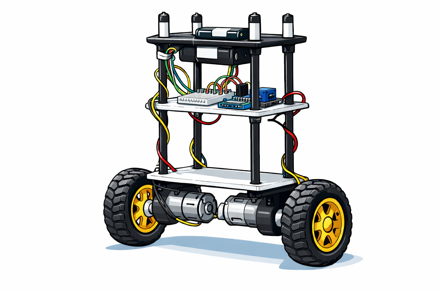
Self-Balancing Robot
[Fall 2025] For our ECE 4760 final project, we built a two-wheeled self-balancing robot that can keep itself upright using real-time feedback control. At its core, the robot behaves like an inverted pendulum, so when it starts to tip, it senses the motion and drives its wheels to bring itself back into balance.
- Suitable forB.Tech/B.E Embedded Systems students
- Build time4-6 weeks
- LevelAdvanced
- Available atAjvika Labs, Kakinada
About this project
For our ECE 4760 final project, we built a two-wheeled self-balancing robot that can keep itself
upright using real-time feedback control. At its core, the robot behaves like an inverted
pendulum, so when it starts to tip, it senses the motion and drives its wheels to bring itself back
into balance.
This project was a chance for us to bring together many of the ideas we learned throughout
ECE 4760 and apply them to a real, physical system. A lot of our design was inspired by
earlier labs and lecture material, especially the old inverted pendulum examples discussed
in class and on the course website, as well as Lab 3, where we used PID control to stabilize
a one-dimensional helicopter. Those exercises gave us intuition for how feedback control
behaves in practice and directly shaped how we approached this project.
The robot is controlled by a Raspberry Pi Pico W running a PID controller on the RP2040
microcontroller. Using data from an onboard IMU, the controller continuously estimates the
robot’s tilt angle and how fast that angle is changing. We combine accelerometer and gyroscope
measurements using a complementary filter, another technique we learned in class, to get a
stable and responsive angle estimate. Based on this information, the controller computes motor
commands at a high rate to keep the robot balanced.
We also wanted the robot to be interactive rather than just balancing in place. To do this, we
built a web-based interface hosted directly on the Pico W, which lets us monitor the robot and
adjust parameters in real time. On top of that, we added gesture-based control so a user can
influence the robot’s motion to move forward or backwards in regards to the tilt of a device.
Throughout the project, we went through several design iterations. Decisions about robot height,
weight distribution, motor placement, and chassis layout all had noticeable effects on control
performance, and testing often forced us to revisit earlier choices. The final robot reflects
this iterative process and captures what we think ECE 4760 is really about: combining theory,
hardware, and software to build something that actually works in the real world.
Demo Video
High Level Design
Our high-level design process began with creating a full 3-D CAD model in Onshape. As a team,
we wanted to fully think through the mechanical structure of the robot before building anything
physically. Modeling the robot in CAD allowed us to reason about dimensions, material choices,
weight distribution, and how all of the subsystems would fit together. This step helped us catch
several potential issues early, particularly related to motor placement, center of mass, and
wiring, before committing to fabrication.
Rather than treating the CAD model as a static drawing, we used it as an iterative design tool.
As our understanding of the physics and control requirements improved, we repeatedly revisited
the model and adjusted the design to better align with our goals for stability, symmetry, and
ease of assembly.
Initial full CAD assembly showing overall robot structure.
View Full CAD Model (Onshape)
Motor Torque and Weight Constraints
One of the first constraints we considered was whether our motors could realistically support
the weight of the robot while still providing enough torque for balance corrections. We selected
48:1 DC gear motors rated at a maximum output torque of 0.078 N·m and paired them with wheels
of radius 5 cm (0.05 m).
To understand what this meant in practice, we related motor torque to the force applied at the
wheel–ground interface using the standard torque relationship:
\( \tau = F r \)
\( F = \frac{\tau}{r} \)
\( F_{\text{motor}} = \frac{0.078}{0.05} = 1.56 \text{ N} \)
Figure 1: Torque-to-force relationship at the wheel.
Since our robot uses two motors, the total available horizontal force is approximately:
\( F_{\text{total}} = 2 \times 1.56 = 3.12 \text{ N} \)
Figure 2: Combined force from both motors.
The completed robot had a total mass of approximately 3 lb (1.36 kg), corresponding to a
gravitational force of:
\( F_g = mg = (1.36)(9.81) \approx 13.3 \text{ N} \)
Figure 3: Gravitational force acting on the robot.
At first glance, this might suggest that the motors are insufficient; however, a self-balancing
robot does not require the motors to lift the robot vertically. Instead, the motors generate
horizontal acceleration of the wheels to correct angular deviations of the inverted pendulum
system. Only a fraction of the robot’s weight contributes to the required corrective torque at
small tilt angles.
This understanding guided our design decisions and gave us confidence that, with appropriate
height selection and PID control, our motors would be capable of stabilizing a 3 lb robot. This
was ultimately confirmed through experimental testing.
Logical System Structure
From a system-level perspective, the robot is organized as a closed-loop feedback system. Sensor
data from the IMU is continuously sampled and filtered to estimate the robot’s orientation. This
estimate is passed to the PID controller, which computes a corrective control signal. That signal
is then translated into PWM commands that drive the motors, completing the feedback loop.
This logical structure influenced both the hardware and software design. Mechanically, we aimed
to create a symmetric, predictable platform so that the control assumptions would hold. In
software, we prioritized deterministic timing and consistent sampling rates to ensure stable
controller behavior.
Effect of Robot Height on Stability
With motor limitations in mind, we spent significant time discussing how tall the robot should
be. Height plays a major role in the dynamics of a self-balancing robot because it determines
the location of the center of mass.
If the robot is too tall, the center of mass is higher, which increases the gravitational torque
during tilt and demands larger corrective torques from the motors. If the robot is too short,
the center of mass lies close to the wheel axle, reducing the gravitational restoring torque and
making the system more sensitive to noise, disturbances, and control latency.
We ultimately chose a moderate height that struck a balance between these two extremes. This
provided a measurable tilt response for the controller while remaining within the torque
capabilities of our motors.
CAD Iterations and Motor Orientation
During CAD development, we explored several motor mounting configurations. One issue we noticed
early was that the motor shafts were slightly offset within the motor housings rather than being
centered.
One idea we considered was mounting the motors horizontally but in opposite orientations so that
the shaft offsets would cancel each other out. While this approach was theoretically sound, it
added mechanical complexity and made precise alignment more difficult.
We ultimately decided to mount the motors vertically, which ensured symmetry about the center
of the robot and simplified both the mechanical assembly and mass distribution. This decision
required us to revise our initial CAD design, but it resulted in a cleaner and more predictable
structure.
Chassis Design and Fabrication
For the overall chassis, we chose to use clear acrylic (plexiglass). The final mechanical
assembly consists of three main acrylic plates forming the body of the robot, six acrylic
interconnect pieces used to attach the motors, four M5 threaded rods, twenty-four M5 nuts,
and plastic adhesive for rigid bonding.
Clear acrylic was chosen primarily because it allowed us to easily see internal components
during assembly and testing. This was especially useful during debugging, as we frequently
needed to inspect wiring, motor drivers, and power connections without disassembling the robot.
Additionally, acrylic can be precisely fabricated using a laser cutter, allowing us to quickly
iterate on our design.
DXF files exported from our Onshape CAD model were submitted to the Rapid Prototyping Lab for
laser cutting. The design intentionally includes slits and openings in the three main plates
to allow wires from the motor circuit, IMU, and battery pack to pass cleanly between layers.
Main frame DXF used to mount motors and wheels.
Supporting frame DXF for motor driver circuit, IMU, and battery pack.
Connector pieces used to attach motors to the main chassis.
Mechanical Adjustments for Tuning and Testing
As we started tuning the PID controller, it became clear very quickly that the robot was going to
fall a lot before it worked well. To avoid damaging the chassis or electronics during these early
tests, we added protective foam around the edges of the robot. This gave the robot a softer
landing when it fell and let us safely experiment with more aggressive PID gains without worrying
about breaking anything.
Foam To Protect Robot on Falls.
We also spent time experimenting with where to place the heavier components on the robot.
The battery pack, which is one of the heaviest parts, was mounted on the top level, while the IMU
and motor driver circuit were placed on the middle level. Putting more weight higher up increased
the height of the center of mass, which made the robot’s tilting motion more noticeable and easier
for the controller to react to during balancing
Technologies used
Hardware components
- RP2040
- Raspberry Pi Pico
- IMU
- gyroscope
- accelerometer
- motor driver
Software & tools
- C
- Arduino IDE
Project demo video
What you get
- Working project / hardware kit, tested before delivery
- Complete source code with explanation
- Project demo and guidance for your viva
- Project report, PPT and IEEE paper support (on request)
Related Embedded Systems projects

Gas Leakage Detector Using Arduino
A budget-friendly LPG gas leak detector built with an Arduino and MQ-5 gas sensor, triggering a buzzer and LED when unsafe gas levels are de...
View project
Simple Alarm System
A beginner-friendly home alarm with PIR motion sensing, keypad PIN entry, and separate entry/exit timing delays, built to be easy to expand.
View project
Ultrasonic Sensor Project with Arduino UNO Q
A beginner-friendly first Arduino UNO Q project: a servo-swept ultrasonic sensor that renders a live sweeping radar display in a web browser...
View project
3D Audio Localization
[Fall 2025] We designed a real-time embedded system that localizes sound sources in three dimensions and visualizes them live using a four-m...
View project