Rotor Rascals drone
[Spring 2025] We built and implemented PID control on a Pico-powered quadcopter to hover on a gimbal stand with throttle input from a controller.
- Suitable forB.Tech/B.E Embedded Systems students
- Build time4-6 weeks
- LevelIntermediate
- Available atAjvika Labs, Kakinada
About this project
RotorRascals Drone
We built and implemented PID control on a Pico-powered quadcopter to hover on a gimbal stand
with throttle input from a controller.
Team Members:
Bryan Peters
Nikolai Nekrutenko
Martin Kostal
RotorRascals assembled drone
A functional quadcopter system powered by a Raspberry Pi Pico, implementing a full
PID-based flight controller from scratch to enable stable hover on a custom gimbal stand was built. Our
goal was to design a hands-on, educational drone platform that could be integrated into ECE and
MAE course curricula, allowing students to work directly with embedded systems, control theory,
and dynamics. Starting from a partially developed hardware prototype and minimal software, we
developed our own PID control logic, tuned it through extensive testing, and integrated
radio-based throttle control. This project not only demonstrated our understanding of embedded
flight control, but also laid the groundwork for a low-cost, reproducible drone platform for
future student use.
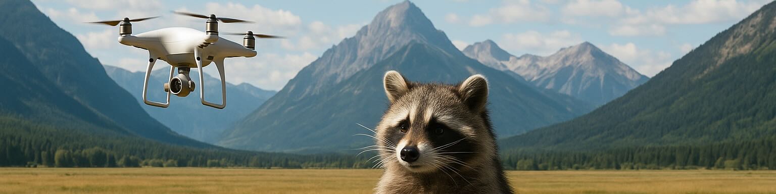
RotorRascal team members flying drones (OpenAI Sora)
High Level Design and Inspiration
Rationale and sources of your project idea
Bryan, Martin and Nikolai enjoy drones and quadcopters, we thought it would be a neat idea to develop
a somewhat functioning flight controller to control the drone with an onboard IMU for
orientation data, an external remote to set the throttle position, and an electronic speed
controller (ESC).
Nikolai is a part of the Motion Studio "Drone Squad" advised by Dr. Beatriz Asfora which was
involved in the creating of this final project idea. Out of the Drone Squad there was already a
prototype developed by Deemo Chen with a PCB integrating an IMU and Pi Pico along with a
skeleton of code on how to control each PWM ESC channel.
The long-term objective of this project is to support the integration of these Pico-based drones
made from 3D printed components into ECE and MAE courses. For instance, these drones could be
integrated in the ECE microcontrollers curriculum and the students could work on code
developing/tuning a PID controller. Or, for a MAE dynamics course, the students could use these
drones for dynamics modelling.
Background Math
The effects of a
P
I
and
D
terms are well known. If we think of controlling
the mass in a spring-mass-damped system, the
P
term acts like increasing the stiffness
of the spring, whereas the
D
term effectively adds damping to the system. An
I
term in general achieves the desirable property of having zero steady state.
Even though our system is not a spring-mass-damped system, we can still keep in mind the above
intuitive properties of each of the three terms of a PID controller.
We ended up using the same set of three
P
I
D
coefficients for
controlling the pitch and the roll angle, and a different set of three
P
I
D
coefficients for the yaw angle. Therefore,
in total.
We did not do any modelling of the drone ("plant") dynamics, and did the tuning by trial and
error. With more time, we would obtain the equations of motion and linearize about the desired
hover position. We would get a linear set of equations, keeping in mind that we should include a
model of noise in the measurements obtained from the IMU. There would be two standard approaches
we could have taken: either design the controller using the state-space approach, or frequency
design. Preceeding each of these two approaches, we would first have to obtain the dynamical
equations of motion from Newton's second law and then linearize them about the desired hover
position.
Getting the dynamical equations of motion would have been non-trivial for several reasons, and
was not achievable in the allocated time for this project. First of all, we would have to obtain
the center of mass and tensor of inertia with respect to the gimbal, treating the drone as a
rigid body. This could have been obtained from a CAD assembly, but only approximately - due to
the geometry of
3D
printed layers, see linked files for the individual parts.
(Furthermore, the chip itself, the IMU, the wiring, the battery would all change these
quantities, and indicate why it would have been really hard to obtain at least a reasonable
model of the dynamics.) Second of all, the friction at the gimbal on the frame of the drone and
the pull of the cables would have to be modelled. The thrust of the propellers in terms of the
duty cycle of our PWM control signal supplied to the motors would be obtained from the
documentation of the propeller's manufacturer. We should keep in mind that the gimbal support
was not located under the center of mass.
Logical Structure
Initialize radio and sensors
Calibrate ESCs and Gyro
Initialize serial PID tuning interface
Wait for arm signal from controller
Erase all stored PID values — effectively reset controls
Spin up motors to minimum throttle and begin executing PID loop
Continue executing PID loop until disarm
Hardware Software Tradeoffs
PID loop speed:
Since the drone is a complicated, unstable system with
4 motors and 6 degrees of freedom, it is vital to have a fast control loop. From
our testing (and Lab 3) we found a rate of 1 kHz works well. Unlike
Lab 3, we must compute PID terms for three axes—pitch, roll, and yaw. Pitch and roll
share the same PID parameters, while yaw uses different parameters discussed later in this
section.
Pico W:
The Pico W provides head-room for future wireless
features. A possible enhancement is a web-based PID-tuning interface where students adjust
sliders and watch live gyro and controller outputs to evaluate PID performance or drone
models.
Controlling 4 Motors:
PWM signals must be calculated for all four
motors (versus a single motor in Lab 3), which greatly increases compute time.
Combining this with multi-axis control means roughly
6 (PID terms) × 3 (axes) × 4 (motors) = 64 × more
computation than Lab 3. Furthermore, changing any motor speed induces torque that
affects the yaw axis—covered in the next point.
Yaw Compensation:
Physical coupling between axes required different PID
weights for yaw than for pitch/roll. In practice the yaw
D
term was reduced
significantly so yaw corrections would not fight the other axes and cause unstable
oscillations.
Long-Term Gyro Drift:
Drift can affect behavior over minutes or hours.
Battery life is only ~ 5 minutes, so this is minor; nevertheless, the gyro recalibrates
each time a battery is plugged in, ensuring reliable short-term attitude estimates.
Existing patents, copyrights, and trademarks which are relevant to our project.
There are no existing patents, copyrights, and trademarks which are relevant to our project.
Program Design
Program Details
The skeleton of code we started from was unnecessarily complicated, so our biggest challenge was
discovering how the actual control algorithms and peripheral interfaces were implemented. The
code for the radio interface was reverse-engineered based on the serial string received from the
controller. Although that was straightforward, it was far less straightforward to implement
pitch, roll, and yaw control from the controller to the rest of the code. Hence, we stuck with
throttle and arm only. From there, we scrapped his PID control as it was unfinished and did not
work and wrote our own. This has its own challenges as we are implementing it on a quadcopter
with four motors. One really important thing that we realized early was that the physical model
for how yaw is controlled is extremely different from how pitch and roll is controlled. This
means we needed separate coefficients for yaw PID and pitch/roll PID. To implement this, we
simply compute the PID values, then apply the coefficients separately in the motor mixing
calculations.
The code has the following structure:
├── main.c # Entry point, initializes hardware and control loop
├── lib/
│ ├── Control/
│ │ ├── controller.c # PID controller logic
│ │ └── controller.h
│ ├── ESC/
│ │ ├── esc.c # Motor PWM control
│ │ └── esc.h
│ ├── Filter/
│ │ ├── leaky_LP.c # Leaky low-pass filter
│ │ └── leaky_LP.h
│ ├── MPU9250/
│ │ ├── mpu9250.c # IMU driver
│ │ └── mpu9250.h
│ ├── Radio/
│ │ ├── radio.c # UART radio input parsing
│ │ └── radio.h
├── include/
│ ├── config.h # System-wide configuration macros
│ └── pins.h # Pin definitions
├── utils/
│ └── math_utils.c/h # Optional math helpers
├── Makefile or CMakeLists # Build system configuration
3D-Printable Files
DIY Drone Frame with Motor Holes:
Onshape link
DIY Drone (Jackson & Dylan) Guards:
Onshape link
DIY Drone Gimbal Interfacer:
Onshape link
Drone Gimbal Mount & Spacer:
Onshape link
Build Guides
Frame 3D-printing guide
Guards 3D-printing guide
Mechanical assembly guide
Electrical assembly / Pico software guide
Getting the Code & Build Environment
# Clone the project
git clone https://github.com/nekrutnikolai/RotorRascal.git
# Go to the software directory
cd RotorRascal/software
# Build the project
./builder
Bill of Materials
Table 1: Drone Components
Component
Part Description
Estimated Price
Frame
3D Printed
$3 – $5 filament
Motors
2306 brushless, 1700–2500 KV
$15 – $30 each
ESC (4-in-1)
30–60 A, DShot600 support
$40 – $80
Propellers
3″ tri-blade props
$3 – $6 set
Radio Receiver (Rx)
ELRS protocol receiver
$15 – $30
Battery
4S LiPo, 1300–1800 mAh
$25 – $50
Table 2: Drone Accesso
We built and implemented PID control on a Pico-powered quadcopter to hover on a gimbal stand
with throttle input from a controller.
Team Members:
Bryan Peters
Nikolai Nekrutenko
Martin Kostal
RotorRascals assembled drone
A functional quadcopter system powered by a Raspberry Pi Pico, implementing a full
PID-based flight controller from scratch to enable stable hover on a custom gimbal stand was built. Our
goal was to design a hands-on, educational drone platform that could be integrated into ECE and
MAE course curricula, allowing students to work directly with embedded systems, control theory,
and dynamics. Starting from a partially developed hardware prototype and minimal software, we
developed our own PID control logic, tuned it through extensive testing, and integrated
radio-based throttle control. This project not only demonstrated our understanding of embedded
flight control, but also laid the groundwork for a low-cost, reproducible drone platform for
future student use.
RotorRascal team members flying drones (OpenAI Sora)
High Level Design and Inspiration
Rationale and sources of your project idea
Bryan, Martin and Nikolai enjoy drones and quadcopters, we thought it would be a neat idea to develop
a somewhat functioning flight controller to control the drone with an onboard IMU for
orientation data, an external remote to set the throttle position, and an electronic speed
controller (ESC).
Nikolai is a part of the Motion Studio "Drone Squad" advised by Dr. Beatriz Asfora which was
involved in the creating of this final project idea. Out of the Drone Squad there was already a
prototype developed by Deemo Chen with a PCB integrating an IMU and Pi Pico along with a
skeleton of code on how to control each PWM ESC channel.
The long-term objective of this project is to support the integration of these Pico-based drones
made from 3D printed components into ECE and MAE courses. For instance, these drones could be
integrated in the ECE microcontrollers curriculum and the students could work on code
developing/tuning a PID controller. Or, for a MAE dynamics course, the students could use these
drones for dynamics modelling.
Background Math
The effects of a
P
I
and
D
terms are well known. If we think of controlling
the mass in a spring-mass-damped system, the
P
term acts like increasing the stiffness
of the spring, whereas the
D
term effectively adds damping to the system. An
I
term in general achieves the desirable property of having zero steady state.
Even though our system is not a spring-mass-damped system, we can still keep in mind the above
intuitive properties of each of the three terms of a PID controller.
We ended up using the same set of three
P
I
D
coefficients for
controlling the pitch and the roll angle, and a different set of three
P
I
D
coefficients for the yaw angle. Therefore,
in total.
We did not do any modelling of the drone ("plant") dynamics, and did the tuning by trial and
error. With more time, we would obtain the equations of motion and linearize about the desired
hover position. We would get a linear set of equations, keeping in mind that we should include a
model of noise in the measurements obtained from the IMU. There would be two standard approaches
we could have taken: either design the controller using the state-space approach, or frequency
design. Preceeding each of these two approaches, we would first have to obtain the dynamical
equations of motion from Newton's second law and then linearize them about the desired hover
position.
Getting the dynamical equations of motion would have been non-trivial for several reasons, and
was not achievable in the allocated time for this project. First of all, we would have to obtain
the center of mass and tensor of inertia with respect to the gimbal, treating the drone as a
rigid body. This could have been obtained from a CAD assembly, but only approximately - due to
the geometry of
3D
printed layers, see linked files for the individual parts.
(Furthermore, the chip itself, the IMU, the wiring, the battery would all change these
quantities, and indicate why it would have been really hard to obtain at least a reasonable
model of the dynamics.) Second of all, the friction at the gimbal on the frame of the drone and
the pull of the cables would have to be modelled. The thrust of the propellers in terms of the
duty cycle of our PWM control signal supplied to the motors would be obtained from the
documentation of the propeller's manufacturer. We should keep in mind that the gimbal support
was not located under the center of mass.
Logical Structure
Initialize radio and sensors
Calibrate ESCs and Gyro
Initialize serial PID tuning interface
Wait for arm signal from controller
Erase all stored PID values — effectively reset controls
Spin up motors to minimum throttle and begin executing PID loop
Continue executing PID loop until disarm
Hardware Software Tradeoffs
PID loop speed:
Since the drone is a complicated, unstable system with
4 motors and 6 degrees of freedom, it is vital to have a fast control loop. From
our testing (and Lab 3) we found a rate of 1 kHz works well. Unlike
Lab 3, we must compute PID terms for three axes—pitch, roll, and yaw. Pitch and roll
share the same PID parameters, while yaw uses different parameters discussed later in this
section.
Pico W:
The Pico W provides head-room for future wireless
features. A possible enhancement is a web-based PID-tuning interface where students adjust
sliders and watch live gyro and controller outputs to evaluate PID performance or drone
models.
Controlling 4 Motors:
PWM signals must be calculated for all four
motors (versus a single motor in Lab 3), which greatly increases compute time.
Combining this with multi-axis control means roughly
6 (PID terms) × 3 (axes) × 4 (motors) = 64 × more
computation than Lab 3. Furthermore, changing any motor speed induces torque that
affects the yaw axis—covered in the next point.
Yaw Compensation:
Physical coupling between axes required different PID
weights for yaw than for pitch/roll. In practice the yaw
D
term was reduced
significantly so yaw corrections would not fight the other axes and cause unstable
oscillations.
Long-Term Gyro Drift:
Drift can affect behavior over minutes or hours.
Battery life is only ~ 5 minutes, so this is minor; nevertheless, the gyro recalibrates
each time a battery is plugged in, ensuring reliable short-term attitude estimates.
Existing patents, copyrights, and trademarks which are relevant to our project.
There are no existing patents, copyrights, and trademarks which are relevant to our project.
Program Design
Program Details
The skeleton of code we started from was unnecessarily complicated, so our biggest challenge was
discovering how the actual control algorithms and peripheral interfaces were implemented. The
code for the radio interface was reverse-engineered based on the serial string received from the
controller. Although that was straightforward, it was far less straightforward to implement
pitch, roll, and yaw control from the controller to the rest of the code. Hence, we stuck with
throttle and arm only. From there, we scrapped his PID control as it was unfinished and did not
work and wrote our own. This has its own challenges as we are implementing it on a quadcopter
with four motors. One really important thing that we realized early was that the physical model
for how yaw is controlled is extremely different from how pitch and roll is controlled. This
means we needed separate coefficients for yaw PID and pitch/roll PID. To implement this, we
simply compute the PID values, then apply the coefficients separately in the motor mixing
calculations.
The code has the following structure:
├── main.c # Entry point, initializes hardware and control loop
├── lib/
│ ├── Control/
│ │ ├── controller.c # PID controller logic
│ │ └── controller.h
│ ├── ESC/
│ │ ├── esc.c # Motor PWM control
│ │ └── esc.h
│ ├── Filter/
│ │ ├── leaky_LP.c # Leaky low-pass filter
│ │ └── leaky_LP.h
│ ├── MPU9250/
│ │ ├── mpu9250.c # IMU driver
│ │ └── mpu9250.h
│ ├── Radio/
│ │ ├── radio.c # UART radio input parsing
│ │ └── radio.h
├── include/
│ ├── config.h # System-wide configuration macros
│ └── pins.h # Pin definitions
├── utils/
│ └── math_utils.c/h # Optional math helpers
├── Makefile or CMakeLists # Build system configuration
3D-Printable Files
DIY Drone Frame with Motor Holes:
Onshape link
DIY Drone (Jackson & Dylan) Guards:
Onshape link
DIY Drone Gimbal Interfacer:
Onshape link
Drone Gimbal Mount & Spacer:
Onshape link
Build Guides
Frame 3D-printing guide
Guards 3D-printing guide
Mechanical assembly guide
Electrical assembly / Pico software guide
Getting the Code & Build Environment
# Clone the project
git clone https://github.com/nekrutnikolai/RotorRascal.git
# Go to the software directory
cd RotorRascal/software
# Build the project
./builder
Bill of Materials
Table 1: Drone Components
Component
Part Description
Estimated Price
Frame
3D Printed
$3 – $5 filament
Motors
2306 brushless, 1700–2500 KV
$15 – $30 each
ESC (4-in-1)
30–60 A, DShot600 support
$40 – $80
Propellers
3″ tri-blade props
$3 – $6 set
Radio Receiver (Rx)
ELRS protocol receiver
$15 – $30
Battery
4S LiPo, 1300–1800 mAh
$25 – $50
Table 2: Drone Accesso
Technologies used
Hardware components
- Raspberry Pi Pico
- IMU
- ADC
Software & tools
- CMake
Project demo video
What you get
- Working project / hardware kit, tested before delivery
- Complete source code with explanation
- Project demo and guidance for your viva
- Project report, PPT and IEEE paper support (on request)
Delivery & Payment
Delivery takes a minimum of two weeks from the date your inquiry is confirmed.
Payment is in two parts:
• 50% advance to start the project
• Remaining 50% before delivery
Note:
• Documentation and PPT are not included by default
• If you need documentation/PPT, it can be arranged for extra time and cost
We'll confirm the exact timeline and cost with you after reviewing your requirements.
Related Embedded Systems projects

Embedded Systems
Gas Leakage Detector Using Arduino
A budget-friendly LPG gas leak detector built with an Arduino and MQ-5 gas sensor, triggering a buzzer and LED when unsafe gas levels are de...
View project
Embedded Systems
Simple Alarm System
A beginner-friendly home alarm with PIR motion sensing, keypad PIN entry, and separate entry/exit timing delays, built to be easy to expand.
View project
Embedded Systems
Ultrasonic Sensor Project with Arduino UNO Q
A beginner-friendly first Arduino UNO Q project: a servo-swept ultrasonic sensor that renders a live sweeping radar display in a web browser...
View project
Embedded Systems
3D Audio Localization
[Fall 2025] We designed a real-time embedded system that localizes sound sources in three dimensions and visualizes them live using a four-m...
View project