Real-Time Julia Set Visualization via Parallel Computing
[Fall 2025] This project implements a real-time, interactive Julia set visualization system using a distributed cluster of RP2040 microcontrollers. A single RP2040 master handles VGA signal generation, frame composition, and user input, while 7 RP2040-based slave nodes form a parallel compute fabric, each leveraging both cores to compute disjoint regions of the fractal. In total,14 compute coresoperate concurrently. To scale computation and communication efficiently, the system introduces acusto
- Suitable forB.Tech/B.E Embedded Systems students
- Build time4-6 weeks
- LevelAdvanced
- Available atAjvika Labs, Kakinada
About this project
ECE 5730 Final Project
Han Wang (hw578@cornell.edu ·
)
Introduction
“Real-Time, Interactive Julia Set Rendering Running on Dual-Core RTOS Leveraging Parallel Computing Clusters of RP2040s with a Custom Interrupt-Driven, Multi-Slave SPI Communication Protocol”
Project overview (TL;DR)
This project implements a real-time, interactive Julia set visualization system using a distributed cluster of RP2040 microcontrollers. A single RP2040 master handles VGA signal generation, frame composition, and user input, while 7 RP2040-based slave nodes form a parallel compute fabric, each leveraging both cores to compute disjoint regions of the fractal. In total,
14 compute cores
operate concurrently. To scale computation and communication efficiently, the system introduces a
custom SPI protocol
featuring
slave-initiated, interrupt-driven transfers, explicit handshaking, and dynamic MISO tri-stating
to prevent bus contention. On the master,
FreeRTOS SMP
(symmetric mulitprocessing) coordinates SPI servicing, rendering, and sensor input across
both cores
, enabling deterministic frame updates and smooth real-time interaction. The result is a tightly integrated system that combines
parallel computing, RTOS scheduling, and low-level protocol design
to push interactive graphics performance on microcontroller-class hardware.
Live Demonstration
Video 1: Real-time julia set visualization via adjusting MPU position
The demo video showcases real-time interaction with the Julia set using an
MPU6050 inertial sensor
. Rotating the device along the
X and Y axes
continuously updates the complex parameter
\(c = c_{re} + i·c_{im}\)
, causing the fractal structure to morph smoothly in real time. Each motion-triggered update forces a full parallel recomputation across all slave nodes, highlighting the system’s low-latency communication pipeline, stable frame timing, and responsiveness under dynamic workloads.
Julia Fractals
A
Julia set
is a fractal generated by iterating a complex-valued function of the form:
\[ z_{n+1} = z_n^2 + c \]
where
\(z\)
and
\(c\)
are complex numbers. For each pixel on the screen, its cooridinate on screen
\((x,y)\)
is corresponded to a cooridinate (
\(z_0\)
= x+ y*i) in the complex plane. The system repeatedly applies the equation and tracks whether the sequence diverges or remains bounded. The
number of iterations before divergence
(
\(\|z\| \geq 2\)
) determines the pixel’s color.
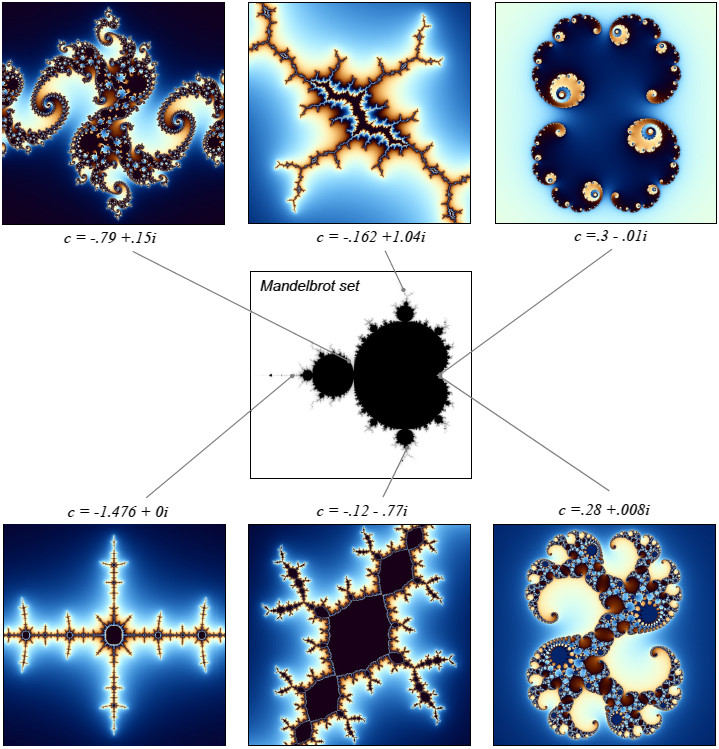
Julia Set and Mandelbrot set (Photo Credit: https://www.karlsims.com/julia.html)
Unlike the Mandelbrot set (which varies
\(c\)
), a Julia set fixes
\(c\)
and visualizes how different starting values
\(z_0\)
evolve. Small changes in
\(c\)
can dramatically alter the global structure, making Julia sets highly sensitive and visually rich—an ideal target for real-time, interactive exploration.
High Level Design
This project implements a
real-time Julia set visualization system
using a distributed cluster of RP2040 microcontrollers. A single RP2040 operates as the master, responsible for VGA signal generation, SPI data receive and service, MPU sensor interaction, and system coordination, while
seven RP2040-based slave nodes
form a parallel computing cluster. Each slave exploits both cores to compute disjoint columns of the Julia set in parallel, yielding
14 concurrent compute cores
dedicated exclusively to fractal generation.
Overview of System Architecture
At the system level, computation and rendering are decoupled through a
customized multi-slave SPI bus
augmented with a dedicated
interrupt line per slave
. Rather than master polling or enforcing rigid transfer schedules, slaves independently signal completion of computation via interrupts and let master initate data transfer. These data-ready signals are aggregated on the master side and serviced by a dedicated
SPI service task
, enabling
slave-initiated, interrupt-driven data transfers
Explicit handshaking commands
and
dynamic MISO tri-stating
ensure that only the active slave RP2040 drives the SPI bus at any time, eliminating contention and allowing the bus to scale safely across multiple active devices.
On the master,
FreeRTOS SMP
orchestrates task execution across
both cores
. A high-priority task (MPU read) continuously reads inertial data from an MPU6050 at certain interval, and broadcasts updated Julia c values to all slaves
spontaneously
via SPI bus. A mid-priority task (SPI service) responds to aggregated slave interrupts, retrieves computed pixel blocks via SPI bus, and enqueues them into a
ring-based draw job buffer
. A lower-priority task asynchronously (VGA draw) consumes these draw jobs by unpacking pixel data and updating the VGA frame buffer. The color data in VGA frame buffer was then translated to VGA screen pattern with a
DMA + PIO
based VGA driver. This task-level separation enables SPI communication, sensor input, and rendering to proceed concurrently with minimal blocking, maintaining deterministic frame timing and smooth real-time interaction.
Program Design
Part I. Slave-Initiated Multi-Slave SPI Bus
Design Challenges
Designing a scalable, real-time communication layer between a single SPI master and multiple active Raspberry Pi slaves exposed several fundamental limitations of conventional SPI usage and the Raspberry Pi C-SDK. These challenges motivated a complete redesign of the SPI protocol.
Key challenges include:
Limited SPI slave support in the Raspberry Pi C-SDK
The SDK’s SPI APIs are primarily designed for master operation and
assume control over CS and SCK
. As a result:
spi_write()
cannot be safely used by a slave.
spi_read()
must be tightly coupled to the master’s
spi_write()
There is no built-in support for multi-slave Raspberry Pi coordination.
Lack of slave-initiated communication
Standard SPI is strictly master-driven. Slaves cannot signal read-ready or request transfers, forcing inefficient polling or rigid scheduling on SPI master — both unacceptable for real-time parallel workloads.
Bus contention on shared SPI MISO lines
RP2040 SPI peripheral continues to
drive MISO low even when peripheral is idle
; Empirical tests show C-SDK’s slave output disable (SOD) bit does not tri-state the MISO pin. So with multiple slaves on a shared MISO line, idle devices cause bus contention and corrupt active transfers.
FIFO timing and synchronization hazards
SPI is sensitive to
TX/RX FIFO timing
. For example, if the master clocks data before the slave has preloaded the FIFO, the master reads invalid or stale data. These hazards are amplified in
half-duplex transmission and interrupt-driven system
where things occur asynchronously.
Need for asynchronous data reception
Slaves must be able to receive parameter updates (e.g., Julia set constants) at any time—without blocking computation or requiring explicit polling loops.
These constraints make a naïve SPI-based multi-slave architecture unreliable and non-scalable this application.
Protocol Overview
To address these challenges, this project implements a
customized, slave-initiated, multi-slave SPI protocol
, illustrated in the diagram below, that redefines the traditional SPI control flow while preserving hardware compatibility.
At a high level, the design augments the standard 4-wire SPI interface with an additional
per-slave interrupt (INT) line
, forming a
5-wire SPI bus
:
SCK, CS, MOSI, MISO, INT
Slave-initiated data transfer (INT + MISO path)
After completing computation for a block of image rows, a slave
asserts its interrupt line
, signaling data readiness.
The master aggregates these interrupts from mulitple slaves and schedules servicing via a dedicated SPI service task.
When master is ready to perform SPI servicing to a particular slave, the master sends an explicit
send-grant command
to that slave. Then starts SPI tramission.
Explicit handshake and FIFO-safe timing control
Slave will first pull the interrupt line high to indicate data ready for transfer. But it only start the transfer sequence (shown below) after receiving the send-grant (
CMD_SEND_DATA
) from master.
Preloads its SPI TX FIFO with the first data word to help with timing control, so that master won’t clock meaningless data.
Dynamically reconnects its MISO pin
to the SPI peripheral by
gpio_set_function()
Waits for CS assertion before clocking out data.
Streams packed pixel data to the master.
Disconnects MISO (set gpio function to
GPIO_FUNC_NULL
) and drains RX FIFO after completion.
Hardware-level contention avoidance
When idle, each slave places its MISO pin in
high-impedance
(
GPIO_FUNC_NULL
) mode.
Only the actively granted slave drives MISO, guaranteeing contention-free operation even with multiple connected slaves.
Asynchronous master-to-slave updates (MOSI path)
The master broadcasts updated Julia parameters using a fixed
data header
(
MASTER_DATA_HEADER
).
On each slave, SPI RX is handled
inside an interrupt service routine
, triggered on the
CS rising edge
The ISR validates the header and either:
Updates the complex parameter
\(c\)
, or
Interprets as a send-grant command.
Slave can now also receive data anytime the master sends it
without calling
spi_read_blocking()
, enabling
real-time data update
Architecture of slave-initated multi-slave SPI bus
Implementation Notes
The slave SPI receive path is implemented in an ISR to capture incoming data
without blocking computation
The send-grant handshake ensures the master is fully prepared to clock data before the slave writes to its TX FIFO.
Timeouts and FIFO resets are used to recover safely from stalled or missed transfers.
The protocol operates in a
half-duplex, message-oriented mode
, rather than conventional full-duplex SPI framing, enabling deterministic timing and clear ownership of the bus.
Completely reconstructed
spi_write()
C-SDK function
designed for RP2040 slaves
is referenced below:
// Modified C-SDK SPI function for slave able to initate data transfer to master
Technologies used
Hardware components
- RP2040
- MPU6050
- ADC
Software & tools
- C
- Arduino IDE
What you get
- Working project / hardware kit, tested before delivery
- Complete source code with explanation
- Project demo and guidance for your viva
- Project report, PPT and IEEE paper support (on request)
Related Embedded Systems projects
Gas Leakage Detector Using Arduino
A budget-friendly LPG gas leak detector built with an Arduino and MQ-5 gas sensor, triggering a buzzer and LED when unsafe gas levels are de...
View project
Simple Alarm System
A beginner-friendly home alarm with PIR motion sensing, keypad PIN entry, and separate entry/exit timing delays, built to be easy to expand.
View project
Ultrasonic Sensor Project with Arduino UNO Q
A beginner-friendly first Arduino UNO Q project: a servo-swept ultrasonic sensor that renders a live sweeping radar display in a web browser...
View project
3D Audio Localization
[Fall 2025] We designed a real-time embedded system that localizes sound sources in three dimensions and visualizes them live using a four-m...
View project