Playing Minecraft with a recorder
[Fall 2022] We created a “keyboard” and “mouse” which are controlled by playing an instrument into a microphone. Each chromatic note between C5 and C6 is assigned to a different keyboard key or mouse movement, which allows us to control a computer using the instrument (which was a recorder in our case). We did this because we felt that the complexity of the project was appropriate for this course and the capability of our group, and because it’s entertaining to be able to play a video game using
- Suitable forB.Tech/B.E Embedded Systems students
- Build time4-6 weeks
- LevelBeginner
- Available atAjvika Labs, Kakinada
About this project
Project Intro
We created a “keyboard” and “mouse” which are controlled by playing
an instrument into a microphone. Each chromatic note between C5 and C6
is assigned to a different keyboard key or mouse movement, which allows
us to control a computer using the instrument (which was a recorder in
our case). We did this because we felt that the complexity of the
project was appropriate for this course and the capability of our group,
and because it’s entertaining to be able to play a video game using a
recorder — a use case which is wholly impractical, but entertaining
because of its novelty.
High Level Design
This project was inspired by a
viral clip
of an
internet personality named Deano Beano who has implemented something
very similar. It’s not clear in this clip how Deano Beano linked his
recorder to the input of his video game, and this is where our own
creativity came in.
In the earlier labs in this class, we constructed circuits and
programs that were able to recognize specific frequencies of audio using
fast Fourier transforms (FFTs) and fixed-point math. This project builds
on this work by integrating it into a more complex system and by
converting that code from C into C++, which makes it easier to write and
less error-prone in conversions between fixed-point numbers, integers,
and floating-point numbers.
Our program is split into a few modules: the FFT module, which is
responsible for collecting samples from the microphone using DMA on the
ADC; the keyboard module, which is responsible for spoofing a USB
keyboard/mouse device; the fpmath module, which encapsulates
floating-point math; the VGA module, which allows us to display
debugging information on a VGA monitor; and the main module, which
coordinates all of these other modules.
Background math
The most important math topics for this project are fixed-point math
and the Fast Fourier Transform.
In our implementation, fixed-point math works by representing the
fractional part of a number in the lower 15 bits of a 32-bit number. To
convert to an integer (truncate), we need only to shift the fixed-point
number right 15 places, and vice versa. To convert to a floating point
number, we can convert the raw representation to a float, and then
divide by 2
. Multiplication and division work by performing
64-bit integer multiplication/division on the two operands and shifting
the result right 15 places. With these routines, we can avoid doing
division and multiplication on floating-point numbers, which is
especially expensive on the Cortex-M0+ processor featured in the
Pico.
The Fast Fourier Transform is not trivial, and it is also extensively
documented by van Hunter Adams on his website, so we include a
link
for brevity.
Tradeoffs
There is a tradeoff between the sampling rate of the microphone (a
higher sampling rate would allow finer frequency analysis, but would
require more processing power), the length of each collection of samples
(a longer collection period would allow finer frequency analysis, but
would make the program less responsive to rapid changes in frequency),
and the accuracy of our frequency analysis. Ultimately, we decided not
to tweak any of these parameters because it was not necessary for our
project to work. The frequency analysis was accurate enough to
distinguish the 12 notes of the scale from each other.
There is also a tradeoff between the spacing of the notes that we
bind to our inputs, and the ease of using the device. If the notes are
spaced further apart, then the user has to be capable of playing a wider
range of notes, which makes the device harder to learn to use, but it
also makes incorrect inputs less likely, and so the device would be more
reliable. We ultimately decided to space our inputs 1 accidental apart
(e.g., C, C#, and D correspond to different inputs).
The version of our device that we demonstrated has the limitation
that the user needs to play the recorder directly into the microphone
for best results. This could be mitigated with a more advanced design
which uses an amplifier (and perhaps a band-pass filter to remove
unwanted frequencies), but we decided that this was not worth the
additional effort.
Patents, copyrights,
trademarks
There are no patents, copyrights, or trademarks that are applicable
to our project, except for the lab code which is copyrighted by van
Hunter Adams. All other code was written by us, or is MIT-licensed.
Program Details
The hardest part of our program to get working consistently was the
FFT. Even though we previously did FFTs in Lab 1 of this course, we
modified the original FFT routine when we converted our code from C to
C++. In doing so, we made a sign error which caused the FFT routine to
fail completely.
Another tricky obstacle we faced arose when we introduced some
spinlocks into our program. We did this to make sure that the parts of
the program which read the results of the FFT were not operating at the
same time as the parts of the program which calculated the results of
the FFT. However, it also introduced a race condition because sometimes
the VGA thread would acquire the spinlock before the FFT thread could
get started. This threw off the timing of the FFT thread and caused it
to produce nonsense. Another symptom of this issue was the entire
program freezing on a static VGA screen upon powering on, but only
sometimes. From this inconsistent behavior we concluded the error was
most likely related to spinlocks. We solved this by adding a short delay
between the start of the FFT thread and the start of the VGA thread.
Once the FFT was working correctly, integrating it with the rest of
the program was fairly straightforward thanks to the fpmath module,
which ensured that any conversions between fixed-point and
non-fixed-point numbers would perform the proper bit-shifting. We
frequently had problems with accidental improper conversions in the
earlier labs in this course where we were expected to use a macro at the
site of each conversion.
Developing the USB functionality of the program was easy at first; we
copied example TinyUSB code from the
Pi
Pico Examples GitHub repository
and adapted it to fit into our
codebase. This code worked without a hitch, so we then got to work
modifying it so that it would produce different keyboard presses based
on which note was being played.
At first, we tried to determine which note was closest to the played
frequency using a logarithmic comparison (since the relationship between
frequency and pitch is logarithmic), but this turned out to be overkill
and we just used a linear comparison.
The keyboard inputs worked smoothly, but the mouse inputs did not
work at first. After a few days of troubleshooting, we discovered that
this was because the function which submits the status of the “mouse” is
called as a callback to the completion of the function which submits the
status of the “keyboard”, and the former was being passed a null pointer
where it was expecting a pointer to the current note’s information.
The mouse movement appears somewhat jerky, and when we use the
device, it produces movement in short jumps instead of smooth horizontal
movement. We attempted to fix this by increasing the frequency with
which we call the TinyUSB periodic tasks (it was 100Hz in the example
code), but this caused the USB code to stop working entirely. We did not
figure out why this happens, so we kept it at the default polling
frequency, which was adequate for our application, which was looking in
different directions in Minecraft.
Hardware Details
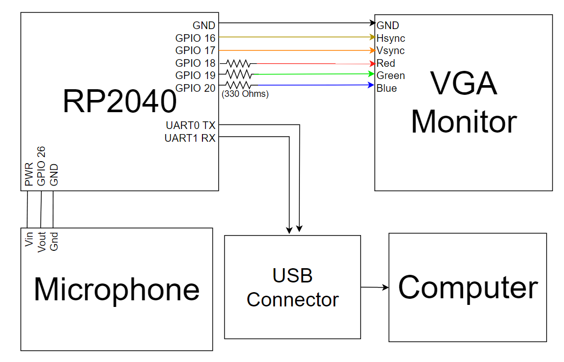
Diagram of Hardware Connections
The hardware connections were relatively simple, since the only
interactive user interface are the notes picked up by the recorder. The
circuit uses a simple 3 pin microphone that is powered from the 3.3v pin
on the pico. It outputs a 0-3.3v analog signal directly into the
built-in ADC of the pico (ADC_0, GP_26). The only other connections
consist of the serial interface, and the VGA screen, which were both
mainly used for debugging, and would theoretically be unused for the
actual “product” itself. The connections are detailed in the code but
are as follows:
GPIO 0 and 1 are used for serial communication
GPIO 16 ---> VGA Hsync
GPIO 17 ---> VGA Vsync
GPIO 18 ---> 330 ohm resistor ---> VGA Red
GPIO 19 ---> 330 ohm resistor ---> VGA Green
GPIO 20 ---> 330 ohm resistor ---> VGA Blue
RP2040 GND ---> VGA GND
GPIO 26 ---> Audio input [0-3.3V]
The connection schemes were carried over from the previous labs using
the same interfaces. The pico is then powered through the host device
that receives the TinyUSB reports through the USB port.
Results of the Design
Testing was primarily done by using pure sine wave generators on our
phones to play tones into the pico’s microphone. We could then use the
VGA screen to confirm that the correct note was being picked up (and
that the background noise was not too loud). The screen displays the
frequency of the largest magnitude, what note that the frequency
“evaluates” to, and the magnitude of the note. The serial print was used
to debug the behavior of the program, we used it to display frequency
information, and sometimes it would also print whenever TinyUSB reports
were given.
The resulting program ran very reliably and was able to quickly pick
up frequencies, and give resulting input commands with little to no
noticeable latency. The screen was also to display clearly, and very
little delay in the FTT graph. The VGA screen makes it so that you can
clearly see what note is being picked up, and how loud, so that in the
case that the system responds unexpectedly, you can quickly see if it is
a volume issue, tone issue, or skill issue. It is also very usable in
that the device simply appears to the computer as a HID usb device, so
no accompanying software or drivers are needed, and it can be run on
virtually any computer.
Conclusion
Our group planned to implement a device that allows a user to use a
recorder as input and we ended u
Technologies used
Hardware components
- RP2040
- microphone
- amplifier
- ADC
Software & tools
- C
- Arduino IDE
What you get
- Working project / hardware kit, tested before delivery
- Complete source code with explanation
- Project demo and guidance for your viva
- Project report, PPT and IEEE paper support (on request)
Related Embedded Systems projects

Gas Leakage Detector Using Arduino
A budget-friendly LPG gas leak detector built with an Arduino and MQ-5 gas sensor, triggering a buzzer and LED when unsafe gas levels are de...
View project
Simple Alarm System
A beginner-friendly home alarm with PIR motion sensing, keypad PIN entry, and separate entry/exit timing delays, built to be easy to expand.
View project
Ultrasonic Sensor Project with Arduino UNO Q
A beginner-friendly first Arduino UNO Q project: a servo-swept ultrasonic sensor that renders a live sweeping radar display in a web browser...
View project
3D Audio Localization
[Fall 2025] We designed a real-time embedded system that localizes sound sources in three dimensions and visualizes them live using a four-m...
View project