Pii bowling
[Spring 2025] This project mirrors a childhood favorite game, Wii Bowling, with a microcontroller twist. Our Wii Bowling implementation utilizes two Raspberry Pi Pico W boards– one as the hand-held controller, and one connected to our VGA display. The controller-system uses an IMU to track the user’s bowling movements and has two buttons to track user inputs. IMU and user input data are sent from the controller to the VGA-system Pico with UDP communication. The Pico W and VGA system runs a bowli
- Suitable forB.Tech/B.E Embedded Systems students
- Build time4-6 weeks
- LevelAdvanced
- Available atAjvika Labs, Kakinada
About this project
Pii Bowling
Introduction
High Level Design
Program/Hardware Design
Results
Conclusion
Appendicies
Pii Bowling
ECE 4760 Spring 2025
Video 1: Demonstration Video
Introduction
This project mirrors a childhood favorite game, Wii Bowling, with a microcontroller twist. Our Wii Bowling implementation utilizes two Raspberry Pi Pico W boards– one as the hand-held controller, and one connected to our VGA display. The controller-system uses an IMU to track the user’s bowling movements and has two buttons to track user inputs. IMU and user input data are sent from the controller to the VGA-system Pico with UDP communication. The Pico W and VGA system runs a bowling physics simulation with the IMU swing data and then displays the ball and pin movements through VGA graphics. We built a cohesive two-player bowling game that includes a classic bowling scoreboard, with all the bowling game logic.
This project presented a unique challenge of creating a playable and believable game, while balancing the difficulties of integrating network communication, hardware peripherals, collision physics, and VGA graphic design. We learned many new things about the game of bowling, including the sometimes complicated intricacies of bowling scores. We also developed a newfound appreciation for game design– taking care to create visuals that were both fun and satisfying to watch.
High Level Design
Pii Bowling was heavily inspired by Wii Bowling, originally designed for the Nintendo Wii. In Wii Bowling, the user can choose the ball’s trajectory angle and release point with their Wii controller. The user then presses a button to track their swing and the game takes into account any spin and their velocity from swing movements. We essentially wanted to imitate this game design but with only one sensor– an IMU. This is where our design and the Wii Bowling game design diverges– since they have an additional optical sensor that tracks where the remote is pointing and gets orientation data (useful for bowling swing trajectory tracking). With our one IMU, and a few buttons, we still mirror the choice of angle and release point, and track the spin and velocity of the bowling ball based on the user’s swing. Our graphics are more simplistic, choosing to display the game from an overhead rather than Wii Bowling’s complex animations.
No existing patents, copyrights, or trademarks were violated in the creation of this project. Although we found inspiration from Wii Bowling, our implementation and design choices diverged to result in a unique adaptation.
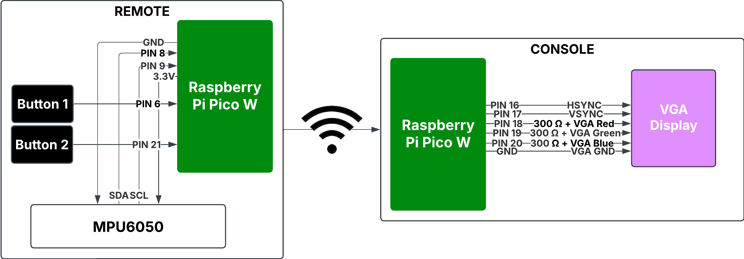
Figure 1: High-level hardware block diagram
The block diagram above shows our high-level hardware design and components. On the remote side, we had two buttons, an IMU and a RPi Pico W. We used two pins, 6 and 21, to hook up the buttons. We used the SDA and SCL connections from pins 8 and 9 to connect the IMU, MPU6050, to our Pico. Additionally, our remote controller was built to be handheld, so we added a battery pack to power the Pico, using pin 39. On the console side, we had another RPi Pico W connected to a VGA display. We used pin 16 for HSYNC, pin 17 for VSYNC, pin 18 for VGA red, pin 19 for VGA green, pin 20 for VGA blue, and hooked up ground.
Background Math
The math can be separated into (1) the motion feature extraction algorithm and the physics engine. We explain the math behind both of those below:
The Motion Feature Extraction (MFE):
The algorithm which we use to turn the raw IMU data which was transferred over UDP into swing data. Firstly, we pass the raw IMU data, including accelerometer and gyroscope readings in X, Y, Z direction of the MPU 6050, in a low-pass filter to smooth the data following this equation:
\( x_i = \alpha x_i + (1-\alpha) x_{i-1}\), where \(\alpha=0.8\), a value we converged to after trying others and observing the most stability without the loss of valuable signal. We then assert the swing is valid, ie. contains a long enough back and forward swing by analyzing the rotational patterns in the Z-axis. Specifically, we look for a negative rotation (below -30°/s) indicating a backswing, followed by a positive rotation (above 40°/s) indicating a forward swing. We require at least 3 frames in each phase, while also checking that the total swing happens within a reasonable timeframe (0.3-3.0 seconds) and follows a natural bowling motion pattern with limited direction changes (1-5). This helps us reject random shaking or invalid movements that don't represent an actual bowling throw.
Finally, we extract the output speed and spin of the balls. We use the gyroscope data which measures the angular velocity of the IMU in degrees and convert it to linear velocity by using the following formula:
\(v=r*\omega*\frac{\pi}{180}\), where \(\omega\) are the values measured by the IMU's gyroscope in degrees and \(r=0.8m\) or the average length of a human arm. Similarly to the preprocessing of the raw data, we use another high-pass filter to calculate the instantaneous changes in motion, which more accurately represents the release characteristics of the ball at the very end of the swing. For the final output, we combine both maximum values and filtered values using weighted averages (50/50 for speed and 35/65 for spin) to balance peak intensity with sustained motion, providing a more realistic representation of how a bowling ball would behave when released from the player's hand.
The Physics Engine:
In general, this portion of the code was responsible for updating the pins and the bowling ball position, velocity, as well as detecting collisions and appropriately dealing with them. The physics engine implements a 2D vector mathematics system to handle movement and interactions, with specialized functions for vector operations (addition, subtraction, scaling, normalization, dot products).
The simulation initializes by translating real-world motion data from the IMU sensors into the virtual environment. The ball's initial position, velocity, and spin are set based on the player's throwing motion. The ball's initial velocity is calculated using trigonometric functions where
v_x = speed * cos(θ)
and
v_y = speed * sin(θ)
, converting the player's release speed and direction angle into component velocities.
For pins, the physics is more complex as it includes both positional and rotational dynamics. Each pin tracks not just position and velocity but also angle and angular velocity. The pin position updates follow the same Euler integration as the ball, but additionally, the angle updates with
angle += angular_velocity * time_delta
. A pin is considered toppled when its absolute angle exceeds
PIN_TOPPLE_THRESHOLD
. In our case, we set that 0.1 as we found it to be the most realistic.
Collision detection uses sphere-based calculations where objects collide if the distance between their centers is less than the sum of their radii. When collisions occur, the engine calculates an impulse-based response that conserves momentum while accounting for elasticity. For a ball-pin collision, a collision normal is calculated as the normalized vector from ball to pin. The impulse magnitude follows the formula:
j = -(1+e) * relative_velocity_along_normal / (1/m_ball + 1/m_pin)
, where e is the elasticity coefficient. This impulse then modifies both objects' velocities proportionally to the inverse of their mass:
v += impulse * (1/mass)
Angular momentum transfer occurs during collisions, creating the realistic pin movement patterns seen in actual bowling. When the ball strikes a pin, part of the linear momentum converts to angular momentum, causing the pin to spin. This is calculated by taking the perpendicular component of the relative velocity:
angular_impulse = dot(perpendicular_vector, relative_velocity) * 0.2
Pin-to-pin collisions follow similar momentum conservation principles but include an additional separation step to prevent pins from overlapping after collision. This separation displacement is calculated as
separation = normal * (2*pin_radius - distance) * 0.5
and applied to both pins in opposite directions.
The simulation also handles gutter events. When the predicted ball position for the next frame would place it beyond either the left or right gutter boundary, the physics engine intervenes with specialized handling and zeroing out the ball's y-velocity component (v_y = 0). This effectively eliminates any lateral movement. Simultaneously, it snaps the ball's position precisely to the gutter edge, setting the y-coordinate to either _left_gutter or _right_gutter depending on which side the ball is approaching from. From this point, the ball continues moving exclusively along the x-axis down the gutter, with only its x-position updating on subsequent frames (position.x += velocity.x * time_delta). Additionally, if the ball moves beyond the lane or its speed drops below a minimum threshold, the simulation is completed, allowing the game to tabulate the score. Below, we include a figure of an example swing where the ball ends up in the gutter:
Figure 2: Example Swing with Gutter Ball
The main physics loop coordinates all these calculations for each frame: updating the ball, checking ball-pin collisions, updating each pin, checking pin-pin collisions, and finally determining if the simulation should end based on the ball's position or speed. This comprehensive physics model captures the essential dynamics of real-world bowling, translating the player's physical motion into an authentic virtual bowling experience. A more realistic engine would have modeled the pins as cylinders but this was simply too complicated to implement and took too long to run. More on this in the later section.
Gameplay Mechanics
Bowling is usually played in 10 frames and two rolls per frame, with the exception of the 10-th frame, in which the user is given three frames as long as all pins are knocked down by
Technologies used
Hardware components
- Raspberry Pi Pico
- VGA display
- IMU
- MPU6050
- gyroscope
- accelerometer
Software & tools
- C
- Arduino IDE
Project demo video
What you get
- Working project / hardware kit, tested before delivery
- Complete source code with explanation
- Project demo and guidance for your viva
- Project report, PPT and IEEE paper support (on request)
Related Embedded Systems projects

Gas Leakage Detector Using Arduino
A budget-friendly LPG gas leak detector built with an Arduino and MQ-5 gas sensor, triggering a buzzer and LED when unsafe gas levels are de...
View project
Simple Alarm System
A beginner-friendly home alarm with PIR motion sensing, keypad PIN entry, and separate entry/exit timing delays, built to be easy to expand.
View project
Ultrasonic Sensor Project with Arduino UNO Q
A beginner-friendly first Arduino UNO Q project: a servo-swept ultrasonic sensor that renders a live sweeping radar display in a web browser...
View project
3D Audio Localization
[Fall 2025] We designed a real-time embedded system that localizes sound sources in three dimensions and visualizes them live using a four-m...
View project