Pico says
[Fall 2023] How's your memorization?Try out our memorization game using 2 Raspberry Pi Pico Ws and wireless communication through UDP!
- Suitable forB.Tech/B.E Embedded Systems students
- Build time4-6 weeks
- LevelBeginner
- Available atAjvika Labs, Kakinada
About this project
Pico Says - ECE4760 Final Report
Project Introduction
How's your memorization?
Try out our memorization game using 2 Raspberry Pi Pico Ws
and wireless communication through UDP!
For our final project, we decided to make a Wi-Fi-based video game
inspired by a popular children's game Simon Says. This is a two player
game, using both LEDs and buttons in front of the player and also a
VGA screen to visually keep track of the game. We chose this final
project because we have been exposed to different communication
protocols but never had any exposure to Wi-Fi and we believed that
this was a cool way to explore it. We specifically used the Raspberry
Pi Pico W’s as our microcontroller and used the lwip library to send
data via Wi-Fi. This was done with access to this library and using
User Datagram Protocol (UDP).
High Level Design
The rationale behind Pico Says was to have two Picos to communicate
with each other using a sequence of LED lights. Each Pico is connected
to 4 LEDs and their corresponding buttons and VGA screen. To pick the
playing, either player can press the reset button to go first, or the
send button to go second. Player One will press whatever LED of their
choice to start the sequence. Player Two will see it on their board
and repeat the sequence that they saw and add onto it. This keeps
going back and forth until one player messes it up. Each player has
three lives before they lose the game. How many lives, the accuracy of
the sequence you sent, and whether it is your turn is all displayed on
the VGA screen.
There were some software tradeoffs as for the Wi-Fi communication
protocol we used was UDP which was a lot easier to implement between
the two Picos but had very little error checking so data can sometimes
get lost after being sent to each board. The other option was TCP
(Transmission Control Protocol) which ensures that the correct data
will always be sent and received but it was a lot harder to implement.
Hardware Design
From the hardware perspective, we had to switch microcontrollers for
the Raspberry Pi Pico to the Raspberry Pi Pico W in order to use the
Wi-Fi capabilities. The pinouts of the boards are very similar which
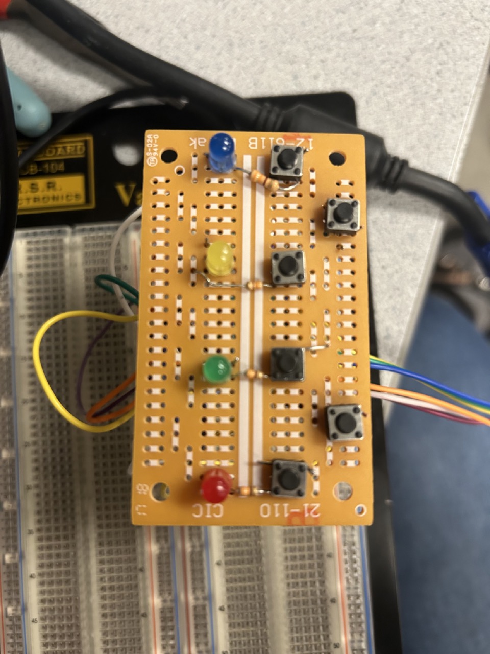
made this transition easier. We soldered the four LEDs, their
respective buttons, and the REST and SEND buttons to prototype boards
As seen above, the order of the LEDs were red, green, and blue. They
are each connected to 330 ohm resistors. The bottom two buttons are
REST and SEND respectively. REST allows a player to start over if they
feel like they made a mistake entering the sequence and once you are
done you send the data using SEND. These buttons also double as
indicating the play order at the beginning of the game. If you select
RESET, you are going first. If you select SEND, you are playing
second. Because we are using two Picos, we had to double everything to
make sure they looked identical and the wirings were the same.
Also connected to the Pico W was a VGA screen to show wheter it was a
player's turn, how many lives were left and the end game result.
The VGA protocol manipulates two digital synchronization pins and three analog color
pins (RED, GREEN, and BLUE) One of the synchronization pins, HSYNC,
tells the screen when to move to a new row of pixels. The other synchronization pin, VSYNC,
tells the screen when to start a new frame. For VGA to work we need send 25MHz red, green, blue
signals through the protocol. The state machine initializes counting registers and waits for a
signal from the VSYNC state machine to start sending pixel data. When active, it clocks out 640
pixels, outputting 3 bits at a time with the required delays. After a row is complete, it resets
and waits for the VSYNC signal. With this protocol, we can now use DMA to communicate pixel data.
How this works is that there is a global character array named vga_data_array holds color data
for pairs of adjacent pixels. This data is sent to the RGB PIO state machine 8 bits at a time
through a DMA channel. The DMA channel is synchronized with the PIO machine using the DREQ_PIO0_TX2
data request signal. Another DMA channel, chained to the first, then resets and reconfigures the first channel.
We implement the software by using DMA to send signals for pixel data. Functions for these have been prewritten
in the VGA Driver Library, so we just need to use those methods in our code.
Software Design
In all three labs we were exposed to SPI, UART and I2C as
communication protocols. However, all these protocols required the
Picos to be wired together. It would be cool to talk and send data
without being confined to a single breadboard. Thus, the idea of using
Wi-Fi was introduced.
This semester we used the Raspberry Pico as our microcontroller. In
order to use Wi-Fi capabilities, we had to move to the Pico W. The
pinouts of the boards are very similar. Once we had our board, we
learned that Wi-Fi has its variety of ways to communicate data. The
two main ones we considered were UDP and TCP. We decided to use UDP
because it was easier to implement and we had example code from
Instructor Bruce Land to start from.
Wi-Fi Implemention
As mentioned, we used example code to frame how the code would be organized.
We organized our code into 5 threads:
UDP Send
This is how each Pico W sends the sequence the players inputs as an array of integers 1-4
(1 = RED, 2 = GREEN, 3 = YELLOW, 4 = BLUE). It is only used when it is signaled to by the Signals
Thread. The majority of this code was from example code listed in our references.
UDP Receive
This takes the incoming sequence from the other picos and translates the array into LED
flashes. This thread also checks if the recieved sequence was accuarate before it was added
to. The majority of this code was from example code listed in our references.
Blink cyw43 LED
This thread is a visual way to represenet if the Pico W's are in pairing mode. Since we used
a hotspot instead of making one of the Pico's a station. We had to wait from both microcontrollers
lights to flicker prior to playing the game otherwise data will not be sent nor recieved. This
compatible to the LWIP library
Serial
This allowed us to see before we draw anything on the VGA screens if the Picos were effectively
communicating with each other. It also ensures they are both connected to the same hotspot. If not data
can not be send nor recieved.
Signals
This controlled all the button presses and LED flashes based on the inputs from the palyer themselves
or that that was received from the other board. It is also where sequences are sent to the UDP send thread
using the SEND button or its clear using RESET. The logic behind signal data transmission happened in here.
We designed the app so that there are three different states of the
game. This is to simplify the process of knowing what to send, We have
a player selection state, a game play state, and an end game state.
These three each contribute to how data is manipulated to send the
correct data and to know what type of data to receive.
Player Selection State:
This state is the starting menu for the game. The design for this
screen is quite simple as it gives each player an overview of the
game, a picture of the hardware that is used to play the game and a
quick instruction on how to start the game.
In order to start the game, the player needs to either press to RESET
button or SEND button. Player selection is first come first serve,
where if one person wants P1 and they press the RESET button, the
other player that has not selected a player will be defaulted to P2.
The reason for this choice is because we did not want to run into
problems where both players wanted to start first. Or a possibility
would be to have both players decide beforehand who wants to receive
or who wants to send a sequence first. This might be more difficult as
we would need to implement a condition or state when both people
playing would accidentally both select the same starting player.
As mentioned previously, the udp send and receive sequence is
dependent state of the game. In this state of the game, we will still
send a sequence but only the first index of the sequence is used. This
first index is used to send the correct player number to the other
pico. The other pico will then determine which player it is, and which
is the other player.
memcpy(otherPlayer, recv_data, send_data_size);
if (otherPlayer == 2) {
player = 1; mode = send;
} else {
player = 2; mode = echo;
}
start_game = true;
Once both players receive the respectful player numbers, we can signal
to both picos that the game is ready to start
Game Playing State
With a completely new state, we can set start_game = true. This is so
that we can change what to check within our sequence. The game state
makes it a little more difficult to know what to send or receive.
Given the instructions of the game, we n
Project Introduction
How's your memorization?
Try out our memorization game using 2 Raspberry Pi Pico Ws
and wireless communication through UDP!
For our final project, we decided to make a Wi-Fi-based video game
inspired by a popular children's game Simon Says. This is a two player
game, using both LEDs and buttons in front of the player and also a
VGA screen to visually keep track of the game. We chose this final
project because we have been exposed to different communication
protocols but never had any exposure to Wi-Fi and we believed that
this was a cool way to explore it. We specifically used the Raspberry
Pi Pico W’s as our microcontroller and used the lwip library to send
data via Wi-Fi. This was done with access to this library and using
User Datagram Protocol (UDP).
High Level Design
The rationale behind Pico Says was to have two Picos to communicate
with each other using a sequence of LED lights. Each Pico is connected
to 4 LEDs and their corresponding buttons and VGA screen. To pick the
playing, either player can press the reset button to go first, or the
send button to go second. Player One will press whatever LED of their
choice to start the sequence. Player Two will see it on their board
and repeat the sequence that they saw and add onto it. This keeps
going back and forth until one player messes it up. Each player has
three lives before they lose the game. How many lives, the accuracy of
the sequence you sent, and whether it is your turn is all displayed on
the VGA screen.
There were some software tradeoffs as for the Wi-Fi communication
protocol we used was UDP which was a lot easier to implement between
the two Picos but had very little error checking so data can sometimes
get lost after being sent to each board. The other option was TCP
(Transmission Control Protocol) which ensures that the correct data
will always be sent and received but it was a lot harder to implement.
Hardware Design
From the hardware perspective, we had to switch microcontrollers for
the Raspberry Pi Pico to the Raspberry Pi Pico W in order to use the
Wi-Fi capabilities. The pinouts of the boards are very similar which
made this transition easier. We soldered the four LEDs, their
respective buttons, and the REST and SEND buttons to prototype boards
As seen above, the order of the LEDs were red, green, and blue. They
are each connected to 330 ohm resistors. The bottom two buttons are
REST and SEND respectively. REST allows a player to start over if they
feel like they made a mistake entering the sequence and once you are
done you send the data using SEND. These buttons also double as
indicating the play order at the beginning of the game. If you select
RESET, you are going first. If you select SEND, you are playing
second. Because we are using two Picos, we had to double everything to
make sure they looked identical and the wirings were the same.
Also connected to the Pico W was a VGA screen to show wheter it was a
player's turn, how many lives were left and the end game result.
The VGA protocol manipulates two digital synchronization pins and three analog color
pins (RED, GREEN, and BLUE) One of the synchronization pins, HSYNC,
tells the screen when to move to a new row of pixels. The other synchronization pin, VSYNC,
tells the screen when to start a new frame. For VGA to work we need send 25MHz red, green, blue
signals through the protocol. The state machine initializes counting registers and waits for a
signal from the VSYNC state machine to start sending pixel data. When active, it clocks out 640
pixels, outputting 3 bits at a time with the required delays. After a row is complete, it resets
and waits for the VSYNC signal. With this protocol, we can now use DMA to communicate pixel data.
How this works is that there is a global character array named vga_data_array holds color data
for pairs of adjacent pixels. This data is sent to the RGB PIO state machine 8 bits at a time
through a DMA channel. The DMA channel is synchronized with the PIO machine using the DREQ_PIO0_TX2
data request signal. Another DMA channel, chained to the first, then resets and reconfigures the first channel.
We implement the software by using DMA to send signals for pixel data. Functions for these have been prewritten
in the VGA Driver Library, so we just need to use those methods in our code.
Software Design
In all three labs we were exposed to SPI, UART and I2C as
communication protocols. However, all these protocols required the
Picos to be wired together. It would be cool to talk and send data
without being confined to a single breadboard. Thus, the idea of using
Wi-Fi was introduced.
This semester we used the Raspberry Pico as our microcontroller. In
order to use Wi-Fi capabilities, we had to move to the Pico W. The
pinouts of the boards are very similar. Once we had our board, we
learned that Wi-Fi has its variety of ways to communicate data. The
two main ones we considered were UDP and TCP. We decided to use UDP
because it was easier to implement and we had example code from
Instructor Bruce Land to start from.
Wi-Fi Implemention
As mentioned, we used example code to frame how the code would be organized.
We organized our code into 5 threads:
UDP Send
This is how each Pico W sends the sequence the players inputs as an array of integers 1-4
(1 = RED, 2 = GREEN, 3 = YELLOW, 4 = BLUE). It is only used when it is signaled to by the Signals
Thread. The majority of this code was from example code listed in our references.
UDP Receive
This takes the incoming sequence from the other picos and translates the array into LED
flashes. This thread also checks if the recieved sequence was accuarate before it was added
to. The majority of this code was from example code listed in our references.
Blink cyw43 LED
This thread is a visual way to represenet if the Pico W's are in pairing mode. Since we used
a hotspot instead of making one of the Pico's a station. We had to wait from both microcontrollers
lights to flicker prior to playing the game otherwise data will not be sent nor recieved. This
compatible to the LWIP library
Serial
This allowed us to see before we draw anything on the VGA screens if the Picos were effectively
communicating with each other. It also ensures they are both connected to the same hotspot. If not data
can not be send nor recieved.
Signals
This controlled all the button presses and LED flashes based on the inputs from the palyer themselves
or that that was received from the other board. It is also where sequences are sent to the UDP send thread
using the SEND button or its clear using RESET. The logic behind signal data transmission happened in here.
We designed the app so that there are three different states of the
game. This is to simplify the process of knowing what to send, We have
a player selection state, a game play state, and an end game state.
These three each contribute to how data is manipulated to send the
correct data and to know what type of data to receive.
Player Selection State:
This state is the starting menu for the game. The design for this
screen is quite simple as it gives each player an overview of the
game, a picture of the hardware that is used to play the game and a
quick instruction on how to start the game.
In order to start the game, the player needs to either press to RESET
button or SEND button. Player selection is first come first serve,
where if one person wants P1 and they press the RESET button, the
other player that has not selected a player will be defaulted to P2.
The reason for this choice is because we did not want to run into
problems where both players wanted to start first. Or a possibility
would be to have both players decide beforehand who wants to receive
or who wants to send a sequence first. This might be more difficult as
we would need to implement a condition or state when both people
playing would accidentally both select the same starting player.
As mentioned previously, the udp send and receive sequence is
dependent state of the game. In this state of the game, we will still
send a sequence but only the first index of the sequence is used. This
first index is used to send the correct player number to the other
pico. The other pico will then determine which player it is, and which
is the other player.
memcpy(otherPlayer, recv_data, send_data_size);
if (otherPlayer == 2) {
player = 1; mode = send;
} else {
player = 2; mode = echo;
}
start_game = true;
Once both players receive the respectful player numbers, we can signal
to both picos that the game is ready to start
Game Playing State
With a completely new state, we can set start_game = true. This is so
that we can change what to check within our sequence. The game state
makes it a little more difficult to know what to send or receive.
Given the instructions of the game, we n
Technologies used
Hardware components
- Raspberry Pi Pico
Software & tools
- C
- Arduino IDE
Project demo video
What you get
- Working project / hardware kit, tested before delivery
- Complete source code with explanation
- Project demo and guidance for your viva
- Project report, PPT and IEEE paper support (on request)
Delivery & Payment
Delivery takes a minimum of two weeks from the date your inquiry is confirmed.
Payment is in two parts:
• 50% advance to start the project
• Remaining 50% before delivery
Note:
• Documentation and PPT are not included by default
• If you need documentation/PPT, it can be arranged for extra time and cost
We'll confirm the exact timeline and cost with you after reviewing your requirements.
Related Embedded Systems projects

Embedded Systems
Gas Leakage Detector Using Arduino
A budget-friendly LPG gas leak detector built with an Arduino and MQ-5 gas sensor, triggering a buzzer and LED when unsafe gas levels are de...
View project
Embedded Systems
Simple Alarm System
A beginner-friendly home alarm with PIR motion sensing, keypad PIN entry, and separate entry/exit timing delays, built to be easy to expand.
View project
Embedded Systems
Ultrasonic Sensor Project with Arduino UNO Q
A beginner-friendly first Arduino UNO Q project: a servo-swept ultrasonic sensor that renders a live sweeping radar display in a web browser...
View project
Embedded Systems
3D Audio Localization
[Fall 2025] We designed a real-time embedded system that localizes sound sources in three dimensions and visualizes them live using a four-m...
View project