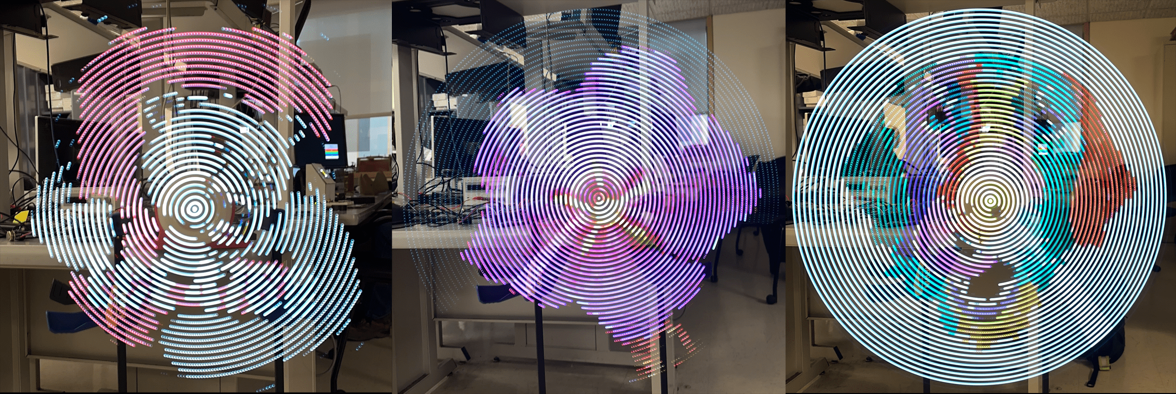
Persistence of vision LED display
[Fall 2022] 30 FPS, full RGB color, and 26” diameter. Updates remotely over WIFI.
- Suitable forB.Tech/B.E Embedded Systems students
- Build time4-6 weeks
- LevelBeginner
- Available atAjvika Labs, Kakinada
About this project
Persistence of Vision Display
30 FPS, full RGB color, and 26" diameter. Updates remotely over WIFI.
View the Project on GitHub
usedhondacivic
Created by: Michael Crum (mmc323@cornell.edu), Joseph Horwitz (jah569@cornell.edu), Rabail Makhdoom
(rm857@cornell.edu)
Project Introduction
Our project is a persistence of vision display constructed from scratch using the Raspberry Pi Pico W
microcontroller. Runs at 30 FPS with full RGB color and streams images over wifi.
Persistence of Vision refers to the eyes’ ability to see images for a brief time after they disappear. Our
display exploits this phenomenon by using a quickly rotating LED strip to “paint” light onto the air. This
creates the illusion of holographic images floating in mid-air. These images are ghostly, beautiful, and
mesmerizing, perfect for advertising, art installations, or product presentations.
Using 40 independently addressable LEDs, we were able to create the illusion of 4800 pixels at over 30 fps. The
display is 26” in diameter, and updates over wifi from our custom python client.
High-Level Design
The original idea for this project came from a video that Rabail saw of a similar POV display on Youtube.com.
We approached our professor, Hunter Adams, to discuss the viability of the project, and after his confirmation,
we started brainstorming ideas Initially, we thought of implementing the display on a propeller fan as we had
seen on Youtube, but eventually, we chose to build the rotor and arm of the POV display ourselves for a cleaner
and more lightweight project.
To display an image, we first convert a bitmap image to a polar coordinate system, where we define a
theoretical “pixel” to be the image’s color at a certain radius from the center of the image at a certain angle.
The resolution of the image in this system is determined by the number of LEDs we can use along its radius and
how many times we can change the LEDs in one rotation.
The logical structure of our project is relatively straightforward. First, our software calculates the time
duration to display each “pixel” on the display by simply measuring the period of each full rotation using a
Hall Effect sensor and a magnet, then dividing by the number of rotation angles we sampled from the source
image. By assigning the LEDs to a certain color for just that duration of time, we can then display the pixels
and ensure proper image orientation at each rotation.
The nature of our design allows the hardware and software tradeoffs to be independent of each other. The more
robust we make our software (i.e. optimized code, error-free LED mapping), the more optimized and error-free our
project becomes. Similarly, by making our hardware more robust (i.e. using heat sinks, tying down wires, using
bigger motors), we get a higher resolution of our system and also make the project safer.
Our project does not include any known existing patents, copyrights, or trademarks. We designed all the
hardware from scratch. The software is also our original work, with some basis in the open-source example code
published by Raspberry Pi.
Design Details
Software
Python Image Preprocessing
Our program had several steps. First, we developed a Python script to convert bitmap images into a custom polar
coordinate data format which can be used to display images on the POV display. The image is represented as a
three-dimensional array of bytes with dimensions of angle along rotation, LED number from center, and R/G/B
color value. This array is generated by sampling pixels from a bitmap image at corresponding angles and radiuses
from the center using NumPy array indexing. Each 0 index LED corresponds to the center pixel of the image and
the outmost LED stretches to the nearest border. Any pixels outside of the circle defined by this radius are
ignored.
Below are some graphs showing what the processed images look like look at varying radial resolutions.
Python TCP Server
The image data is sent to the Pico through a Transmission Control Protocol (TCP) socket using the Python socket
library. To do this, the full array is divided up into packets consisting of the data for two orientations of
the arm. Each packet is flattened and converted into a byte array, then sent to the Pico W. We chose to use a
TCP protocol as it is reliable and accurate. It works by establishing a connection with the client via a 3-way
handshake process. We then send packets to the client over TCP and each packet is acknowledged before the next
one is sent. Below is the TCP server function given a preprocessed image array.
def send_arr(rot_arr, debug=False):
# Open socket to the server
sock = socket.socket()
addr = ('0.0.0.0', SERVER_PORT)
sock.bind(addr)
sock.listen(1)
print('server listening on', addr)
# Wait for the client
con = None
con, addr = sock.accept()
print('client connected from', addr)
total_bytes = 0
# repeat test for a number of iterations
for i in range(PACKET_NUM):
# Take RPB rotations from image
curr_data = rot_arr[RPB*i : RPB*i+RPB][:][:]
write_buf = bytearray(curr_data.flatten())
if debug:
print(len(curr_data.flatten()))
print(len(write_buf))
prstr = ""
for i, b in enumerate(write_buf):
if i % 3 == 0: prstr += 'r: ' + str(int(b)) + ' '
if i % 3 == 1: prstr += 'g: ' + str(int(b)) + ' '
if i % 3 == 2: prstr += 'b: ' + str(int(b)) + '\n'
print(prstr)
# write BUF_SIZE bytes to the client
write_len = con.send(write_buf)
print('Wrote %d bytes to client' % write_len)
total_bytes += write_len
# Check size of data written
if write_len != BUF_SIZE:
raise RuntimeError('wrong amount of data written')
# All done
con.close()
sock.close()
print(f"In total wrote {total_bytes} bytes")
print("send completed")
APA102 LEDs
The APA102 LEDs use a two-wire SPI protocol to communicate with the PI Pico. This allows us to use RP2040’s SPI
peripheral, which made writing the driver easy. The LEDs expect packets that are broken into “frames” of 32
bits. Each message begins with a start frame of 32 0’s, and ends with an end frame of 32 1’s. In between, each
frame represents the data for a single LED in the strip. A LED frame starts with 111, then is followed by five
bits representing the brightness of the LED. This is followed by 8 bits for each of blue, green, and red, giving
256 values for each.
Below is our code for constructing the packets based on a three-dimensional array representing the color of
each LED on the strip.
void apa102_write_strip(uint8_t (*color_data)[3], uint16_t num_leds)
{
uint8_t spi_buffer[num_leds * 4 + 8];
// Start frame
spi_buffer[0] = 0x00;
spi_buffer[1] = 0x00;
spi_buffer[2] = 0x00;
spi_buffer[3] = 0x00;
// LED frames
for (int i = 0; i < num_leds; i++)
{
if (i < 5) // Inner most LEDs move slower, so appear brighter. Lower their brightness
{
spi_buffer[i * 4 + 4] = 0b11100001; // Not full brightness so I don't kill my retinas
}
else
{
spi_buffer[i * 4 + 4] = 0b11100011; // Not full brightness so I don't kill my retinas
}
// APA102's we have are RBG instead of RGB,so flip the BG inputs here.
spi_buffer[i * 4 + 5] = color_data[i][0];
spi_buffer[i * 4 + 6] = color_data[i][2];
spi_buffer[i * 4 + 7] = color_data[i][1];
}
// End frame
spi_buffer[num_leds * 4 + 4] = 0xFF;
spi_buffer[num_leds * 4 + 5] = 0xFF;
spi_buffer[num_leds * 4 + 6] = 0xFF;
spi_buffer[num_leds * 4 + 7] = 0xFF;
spi_write_blocking(SPI_PORT, spi_buffer, num_leds * 4 + 8);
}
The LEDs are wired in series, with the SCK and MOSI lines of the previous LED leading into the next. When an
LED receives a packet, it updates its state, strips the first LED frame off the packet, and then shifts the new
packet out of its output SCK and MOSI lines. By doing so the entire strip can be updated from a single message
sent to the first LED in the strip.
Hall Effect Sensor
The hall effect sensor we chose is active low, meaning it pulls a GPIO pin to ground whenever the south pole of
a magnet gets close to it. We set up a falling edge interrupt on the pin, triggering whenever the sensor moves
past the stationary magnet on the motor mount. Below is the code inside of the interrupt:
detect_time = time_us_32();
if (detect_time - old_time > 10000)
{
time_period = detect_time - old_time;
old_time = detect_time;
curr_rot = 0;
}
When the interrupt is triggered, the period of rotation is calculated by subtracting the last activation from
the current time. We also check that the period is a reasonable value (> 10000 us), which helps us reject any
high-frequency false positives. Finally, we indicate that we have hit our zero point by setting the relevant
variable. This stops the display from becoming misaligned relative to the external reference frame.
Pico TCP Client
Then, we established a TCP exchange to transfer the processed image data to the microcontroller which operates
the display. We based this code on the open-source TCP examples provided by Raspberry Pi for the Pico W. Wifi
was our chosen communication method because it allowed us to update the image while the microcontroller was
rotating, which would be impossible with a wired setup. On the microcontroller’s side, we had one thread poll
for incoming data and handle processing that data, w
30 FPS, full RGB color, and 26" diameter. Updates remotely over WIFI.
View the Project on GitHub
usedhondacivic
Created by: Michael Crum (mmc323@cornell.edu), Joseph Horwitz (jah569@cornell.edu), Rabail Makhdoom
(rm857@cornell.edu)
Project Introduction
Our project is a persistence of vision display constructed from scratch using the Raspberry Pi Pico W
microcontroller. Runs at 30 FPS with full RGB color and streams images over wifi.
Persistence of Vision refers to the eyes’ ability to see images for a brief time after they disappear. Our
display exploits this phenomenon by using a quickly rotating LED strip to “paint” light onto the air. This
creates the illusion of holographic images floating in mid-air. These images are ghostly, beautiful, and
mesmerizing, perfect for advertising, art installations, or product presentations.
Using 40 independently addressable LEDs, we were able to create the illusion of 4800 pixels at over 30 fps. The
display is 26” in diameter, and updates over wifi from our custom python client.
High-Level Design
The original idea for this project came from a video that Rabail saw of a similar POV display on Youtube.com.
We approached our professor, Hunter Adams, to discuss the viability of the project, and after his confirmation,
we started brainstorming ideas Initially, we thought of implementing the display on a propeller fan as we had
seen on Youtube, but eventually, we chose to build the rotor and arm of the POV display ourselves for a cleaner
and more lightweight project.
To display an image, we first convert a bitmap image to a polar coordinate system, where we define a
theoretical “pixel” to be the image’s color at a certain radius from the center of the image at a certain angle.
The resolution of the image in this system is determined by the number of LEDs we can use along its radius and
how many times we can change the LEDs in one rotation.
The logical structure of our project is relatively straightforward. First, our software calculates the time
duration to display each “pixel” on the display by simply measuring the period of each full rotation using a
Hall Effect sensor and a magnet, then dividing by the number of rotation angles we sampled from the source
image. By assigning the LEDs to a certain color for just that duration of time, we can then display the pixels
and ensure proper image orientation at each rotation.
The nature of our design allows the hardware and software tradeoffs to be independent of each other. The more
robust we make our software (i.e. optimized code, error-free LED mapping), the more optimized and error-free our
project becomes. Similarly, by making our hardware more robust (i.e. using heat sinks, tying down wires, using
bigger motors), we get a higher resolution of our system and also make the project safer.
Our project does not include any known existing patents, copyrights, or trademarks. We designed all the
hardware from scratch. The software is also our original work, with some basis in the open-source example code
published by Raspberry Pi.
Design Details
Software
Python Image Preprocessing
Our program had several steps. First, we developed a Python script to convert bitmap images into a custom polar
coordinate data format which can be used to display images on the POV display. The image is represented as a
three-dimensional array of bytes with dimensions of angle along rotation, LED number from center, and R/G/B
color value. This array is generated by sampling pixels from a bitmap image at corresponding angles and radiuses
from the center using NumPy array indexing. Each 0 index LED corresponds to the center pixel of the image and
the outmost LED stretches to the nearest border. Any pixels outside of the circle defined by this radius are
ignored.
Below are some graphs showing what the processed images look like look at varying radial resolutions.
Python TCP Server
The image data is sent to the Pico through a Transmission Control Protocol (TCP) socket using the Python socket
library. To do this, the full array is divided up into packets consisting of the data for two orientations of
the arm. Each packet is flattened and converted into a byte array, then sent to the Pico W. We chose to use a
TCP protocol as it is reliable and accurate. It works by establishing a connection with the client via a 3-way
handshake process. We then send packets to the client over TCP and each packet is acknowledged before the next
one is sent. Below is the TCP server function given a preprocessed image array.
def send_arr(rot_arr, debug=False):
# Open socket to the server
sock = socket.socket()
addr = ('0.0.0.0', SERVER_PORT)
sock.bind(addr)
sock.listen(1)
print('server listening on', addr)
# Wait for the client
con = None
con, addr = sock.accept()
print('client connected from', addr)
total_bytes = 0
# repeat test for a number of iterations
for i in range(PACKET_NUM):
# Take RPB rotations from image
curr_data = rot_arr[RPB*i : RPB*i+RPB][:][:]
write_buf = bytearray(curr_data.flatten())
if debug:
print(len(curr_data.flatten()))
print(len(write_buf))
prstr = ""
for i, b in enumerate(write_buf):
if i % 3 == 0: prstr += 'r: ' + str(int(b)) + ' '
if i % 3 == 1: prstr += 'g: ' + str(int(b)) + ' '
if i % 3 == 2: prstr += 'b: ' + str(int(b)) + '\n'
print(prstr)
# write BUF_SIZE bytes to the client
write_len = con.send(write_buf)
print('Wrote %d bytes to client' % write_len)
total_bytes += write_len
# Check size of data written
if write_len != BUF_SIZE:
raise RuntimeError('wrong amount of data written')
# All done
con.close()
sock.close()
print(f"In total wrote {total_bytes} bytes")
print("send completed")
APA102 LEDs
The APA102 LEDs use a two-wire SPI protocol to communicate with the PI Pico. This allows us to use RP2040’s SPI
peripheral, which made writing the driver easy. The LEDs expect packets that are broken into “frames” of 32
bits. Each message begins with a start frame of 32 0’s, and ends with an end frame of 32 1’s. In between, each
frame represents the data for a single LED in the strip. A LED frame starts with 111, then is followed by five
bits representing the brightness of the LED. This is followed by 8 bits for each of blue, green, and red, giving
256 values for each.
Below is our code for constructing the packets based on a three-dimensional array representing the color of
each LED on the strip.
void apa102_write_strip(uint8_t (*color_data)[3], uint16_t num_leds)
{
uint8_t spi_buffer[num_leds * 4 + 8];
// Start frame
spi_buffer[0] = 0x00;
spi_buffer[1] = 0x00;
spi_buffer[2] = 0x00;
spi_buffer[3] = 0x00;
// LED frames
for (int i = 0; i < num_leds; i++)
{
if (i < 5) // Inner most LEDs move slower, so appear brighter. Lower their brightness
{
spi_buffer[i * 4 + 4] = 0b11100001; // Not full brightness so I don't kill my retinas
}
else
{
spi_buffer[i * 4 + 4] = 0b11100011; // Not full brightness so I don't kill my retinas
}
// APA102's we have are RBG instead of RGB,so flip the BG inputs here.
spi_buffer[i * 4 + 5] = color_data[i][0];
spi_buffer[i * 4 + 6] = color_data[i][2];
spi_buffer[i * 4 + 7] = color_data[i][1];
}
// End frame
spi_buffer[num_leds * 4 + 4] = 0xFF;
spi_buffer[num_leds * 4 + 5] = 0xFF;
spi_buffer[num_leds * 4 + 6] = 0xFF;
spi_buffer[num_leds * 4 + 7] = 0xFF;
spi_write_blocking(SPI_PORT, spi_buffer, num_leds * 4 + 8);
}
The LEDs are wired in series, with the SCK and MOSI lines of the previous LED leading into the next. When an
LED receives a packet, it updates its state, strips the first LED frame off the packet, and then shifts the new
packet out of its output SCK and MOSI lines. By doing so the entire strip can be updated from a single message
sent to the first LED in the strip.
Hall Effect Sensor
The hall effect sensor we chose is active low, meaning it pulls a GPIO pin to ground whenever the south pole of
a magnet gets close to it. We set up a falling edge interrupt on the pin, triggering whenever the sensor moves
past the stationary magnet on the motor mount. Below is the code inside of the interrupt:
detect_time = time_us_32();
if (detect_time - old_time > 10000)
{
time_period = detect_time - old_time;
old_time = detect_time;
curr_rot = 0;
}
When the interrupt is triggered, the period of rotation is calculated by subtracting the last activation from
the current time. We also check that the period is a reasonable value (> 10000 us), which helps us reject any
high-frequency false positives. Finally, we indicate that we have hit our zero point by setting the relevant
variable. This stops the display from becoming misaligned relative to the external reference frame.
Pico TCP Client
Then, we established a TCP exchange to transfer the processed image data to the microcontroller which operates
the display. We based this code on the open-source TCP examples provided by Raspberry Pi for the Pico W. Wifi
was our chosen communication method because it allowed us to update the image while the microcontroller was
rotating, which would be impossible with a wired setup. On the microcontroller’s side, we had one thread poll
for incoming data and handle processing that data, w
Technologies used
Hardware components
- RP2040
- Raspberry Pi Pico
- DAC
Software & tools
- Python
Project demo video
What you get
- Working project / hardware kit, tested before delivery
- Complete source code with explanation
- Project demo and guidance for your viva
- Project report, PPT and IEEE paper support (on request)
Delivery & Payment
Delivery takes a minimum of two weeks from the date your inquiry is confirmed.
Payment is in two parts:
• 50% advance to start the project
• Remaining 50% before delivery
Note:
• Documentation and PPT are not included by default
• If you need documentation/PPT, it can be arranged for extra time and cost
We'll confirm the exact timeline and cost with you after reviewing your requirements.
Related Embedded Systems projects

Embedded Systems
Gas Leakage Detector Using Arduino
A budget-friendly LPG gas leak detector built with an Arduino and MQ-5 gas sensor, triggering a buzzer and LED when unsafe gas levels are de...
View project
Embedded Systems
Simple Alarm System
A beginner-friendly home alarm with PIR motion sensing, keypad PIN entry, and separate entry/exit timing delays, built to be easy to expand.
View project
Embedded Systems
Ultrasonic Sensor Project with Arduino UNO Q
A beginner-friendly first Arduino UNO Q project: a servo-swept ultrasonic sensor that renders a live sweeping radar display in a web browser...
View project
Embedded Systems
3D Audio Localization
[Fall 2025] We designed a real-time embedded system that localizes sound sources in three dimensions and visualizes them live using a four-m...
View project