Optical microphone
[Spring 2025] Audio capture using laser-reflected surface vibrations - no contact, no mic, just light.
- Suitable forB.Tech/B.E Embedded Systems students
- Build time4-6 weeks
- LevelAdvanced
- Available atAjvika Labs, Kakinada
About this project
Introduction
Audio capture using laser-reflected surface vibrations - no contact, no mic, just light.
Introduction Video
Listening to Mirrors by Justin Timberlake
Abstract
This project demonstrates the feasibility of an optical microphone system that captures sound through vibrations detected by a reflected laser beam. By aiming a laser diode at a vibrating reflective surface and measuring fluctuations in the reflected light intensity using a photodiode, we convert mechanical vibrations caused by sound into electrical signals. These signals are filtered, digitized, processed, and ultimately played back through a speaker. Our implementation includes both analog and digital signal processing on a Raspberry Pi Pico microcontroller. The final system reliably reproduces audio and demonstrates how light can be used to perceive sound, with performance evaluated across varying distances using signal-to-noise ratio (SNR) measurements.
We chose to pursue this project because we were intrigued by the idea of non-contact sound detection using light, a technology that has been used in espionage and surveillance for decades. The concept of "hearing through walls" using only a laser beam and a sensor was both technically challenging and intellectually stimulating. By building an optical microphone, we hoped to gain a deeper understanding of analog and digital signal processing, optics, and real-world system integration. This project also presented an opportunity to explore the intersection of electronics, acoustics, and photonics in a novel application.
High Level Design
The design of our optical microphone system is rooted in the fundamental physics of wave propagation, photodetection, and analog signal processing. The core idea, to detect sound remotely via laser reflection, draws inspiration from historical espionage techniques and more recent DIY laser microphone builds, such as those popularized in the video “I Built a CIA Spy Device (Laser Mic)” (2025).
At a high level, the system operates by converting sound-induced surface vibrations into light intensity modulations, which are then transduced by a photodiode into voltage signals. These signals undergo analog conditioning (amplification, filtering, biasing) before being digitized by the Raspberry Pi Pico, processed, and converted back to analog audio for playback.
Using off-the-shelf components kept the design cost-effective while ensuring performance. While we did not find active patents blocking educational prototyping of optical microphones, commercial systems exist,2 and copyright protections may apply to proprietary implementations. However, our system remains open-source and educational in nature, with all components, code, and designs based on publicly available principles and datasheets.
Concepts
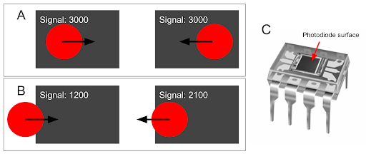
This project focuses on building a low-cost, portable optical microphone system. Unlike traditional microphones that directly detect sound pressure, an optical microphone leverages the principle that sound waves cause small but detectable vibrations in objects. When a laser beam reflects off such a vibrating surface, the intensity and direction of the reflected beam change subtly. A photodiode detects these changes, which can be translated back into sound via signal processing. The alignment of the beam to the photodiode is extremely important for this change to be detected. The focus of the beam should only be on half of the photodiode’s surface for effective detection of change as illustrated in Figure 1. Specifically, we used the OPT101 that has a flat rectangular surface as its receiver.
Figure 1.
Figure 1. Gray rectangle is the photodiode surface and the red circle is the Laser beam wavefront. A) The laser beam completely overlaps the photodiode which causes no change in overall light intensity with vibration. B) The laser beam is slightly overlapped with the photodiode so that any vibrational change is translated to light intensity change. C) OPT101 figure with photodiode surface.
A vibrating surface modulates the phase and angle of the reflected laser light. This modulation alters the intensity captured by the photodiode due to the beam's displacement over its active area. These fluctuations are converted to voltage, passed through analog filters to remove noise, digitized, processed with filtering and then converted back to analog audio signals for playback.
Design and Testing
Hardware Description
The following table lists all components used in this project including a short description, source, and cost of materials.
Component
Description
Source
Cost ($)
OPT101
Monolithic photodiode and transimpedance amplifier
Amazon
22.72
Laser Diode
Class II laser for safe optical transmission
Amazon
13.97
LM358P
Operational amplifiers for analog filtering
Lab supply
0.00
Resistors & Capacitors
For analog circuitry
Lab supply
0.00
MCP4822
Digital-to-Analog Converter
Lab supply
0.00
TLE2426CP
Rail splitter to create virtual ground
DigiKey
2.67
Speaker & Audio Jack
Output for sound
Lab supply
0.00
Pi Pico
Microcontroller handling signal acquisition and processing
Provided
0.00
Reflective Surface
Thin plastic window mounted on a box
UPS Store/Custom
3.50
Helping Hands
Small metal stand with clips to mount laser diode and OPT101
Amazon
9.99
TOTAL
52.85
Table 1. Bill of Materials
Mechanical Setup
Figure 2.
Whole setup. The oscilloscope probes the signal inputted into the Pi Pico analog pin. The emitting laser diode is about 2 feet away from the “Window” encasing a speaker. The OPT101 is on the same stand as the laser diode and breadboard.
Figure 2 illustrates the optical alignment setup, designed to maximize signal fidelity and reduce interference during operation. In our configuration, the laser diode was positioned to direct a coherent beam toward a reflective surface mounted within a thin cardboard enclosure. The reflected beam was then directed onto the active region of the OPT101 photodiode. To ensure optimal alignment, both the laser and photodiode were mounted on adjustable stands, allowing for fine-tuned angular and positional control. The breadboard containing the analog circuitry was also stationed on top of the black mounting surface to prevent unintended movements from all the jumper wires.
Alignment
The cardboard enclosure was custom made and consists of an envelope and cut out plastic piece from a plastic container. Chosen based on experimentation, the integrity of the plastic cut out offered better signal fidelity than other materials like aluminum foil due to consistent reflectivity and minimal distortion. It also replicated reflecting off an actual window. Foil, while shiny, introduced unpredictable refraction and was prone to crinkling, which distorted the laser reflection. In contrast, the thin plastic sheet provided a stable, smooth surface that yielded significantly clearer and more consistent audio signals due to its surface uniformity and rigidity. This choice allowed for facilitated alignment.
Figure 3.
Close up of photodiode and laser diode configuration on helping hands.
To further improve signal quality and minimize noise, the photodiode was encased in a custom-made black tube constructed from matte black tape. This improvised light shield served a crucial function: it blocked ambient light from surrounding sources, such as overhead fluorescent lights or sunlight from windows, which could otherwise saturate or distort the photodiode’s output. Without this shielding, the OPT101 would often saturate when exposed to strong ambient light, rendering it unable to detect subtle fluctuations in laser intensity caused by surface vibrations.
By narrowing the photodiode’s field of view to accept only the focused reflection from the laser, the black tube helped isolate the desired signal and significantly improved the signal-to-noise ratio (SNR) of our measurements. This setup ensured that the variations in photodiode output were due to the modulated reflected laser light alone, preserving the integrity of the vibration-induced signal and enabling reliable downstream audio reconstruction.
Electrical Setup
The Raspberry Pi Pico was used as the central microcontroller for its fast processing capabilities, built-in 12-bit ADC, and precise timing control using hardware interrupts. It enabled real-time sampling of the photodiode signal, performed digital signal processing, and interfaced seamlessly with the DAC for audio playback, all while maintaining a low-cost and compact footprint.
Laser Diode
We used a laser diode because it provides a coherent, narrow beam ideal for accurately reflecting off vibrating surfaces. A consistent, high-intensity beam ensures that small changes in angle or surface displacement result in measurable variations in the detected signal. The cathode is connected to ground and anode is connected to 3.3V of the Pi Pico.
OPT101 Photodiode
Photodiodes convert light fluctuations to voltage. The OPT101 was selected for its simplicity and precision. It combines a photodiode and a high-gain amplifier in one 8-pin package, minimizing the need for external components. Its analog output responds proportionally to incident light, which is essential for detecting subtle intensity changes due to vibration-modulated reflection
Figure 4.
OPT101 pin configuration.
For proper operation, the power (pin 1, Vs) is set to 3.3 V from the Pi Pico relative to the most negative supply (pin 3, -V), which is connected to the ground of the Pico. The output voltage corresponding to the photodiode signal is available at pin 5 (Output) with pin 4 (1 MΩ Feedback). Pin 2 (-In) and pin 8 (Common) are connected to ground. This pin configuration supports straightforward integration into analog circuits, allowing precise detection of light intensity with minimal external components.
Rail Splitter
The TLE2426CP chip is used to create a virtual ground that is in the midpoint of a voltage supply to be used by all op amps.
Figure
Audio capture using laser-reflected surface vibrations - no contact, no mic, just light.
Introduction Video
Listening to Mirrors by Justin Timberlake
Abstract
This project demonstrates the feasibility of an optical microphone system that captures sound through vibrations detected by a reflected laser beam. By aiming a laser diode at a vibrating reflective surface and measuring fluctuations in the reflected light intensity using a photodiode, we convert mechanical vibrations caused by sound into electrical signals. These signals are filtered, digitized, processed, and ultimately played back through a speaker. Our implementation includes both analog and digital signal processing on a Raspberry Pi Pico microcontroller. The final system reliably reproduces audio and demonstrates how light can be used to perceive sound, with performance evaluated across varying distances using signal-to-noise ratio (SNR) measurements.
We chose to pursue this project because we were intrigued by the idea of non-contact sound detection using light, a technology that has been used in espionage and surveillance for decades. The concept of "hearing through walls" using only a laser beam and a sensor was both technically challenging and intellectually stimulating. By building an optical microphone, we hoped to gain a deeper understanding of analog and digital signal processing, optics, and real-world system integration. This project also presented an opportunity to explore the intersection of electronics, acoustics, and photonics in a novel application.
High Level Design
The design of our optical microphone system is rooted in the fundamental physics of wave propagation, photodetection, and analog signal processing. The core idea, to detect sound remotely via laser reflection, draws inspiration from historical espionage techniques and more recent DIY laser microphone builds, such as those popularized in the video “I Built a CIA Spy Device (Laser Mic)” (2025).
At a high level, the system operates by converting sound-induced surface vibrations into light intensity modulations, which are then transduced by a photodiode into voltage signals. These signals undergo analog conditioning (amplification, filtering, biasing) before being digitized by the Raspberry Pi Pico, processed, and converted back to analog audio for playback.
Using off-the-shelf components kept the design cost-effective while ensuring performance. While we did not find active patents blocking educational prototyping of optical microphones, commercial systems exist,2 and copyright protections may apply to proprietary implementations. However, our system remains open-source and educational in nature, with all components, code, and designs based on publicly available principles and datasheets.
Concepts
This project focuses on building a low-cost, portable optical microphone system. Unlike traditional microphones that directly detect sound pressure, an optical microphone leverages the principle that sound waves cause small but detectable vibrations in objects. When a laser beam reflects off such a vibrating surface, the intensity and direction of the reflected beam change subtly. A photodiode detects these changes, which can be translated back into sound via signal processing. The alignment of the beam to the photodiode is extremely important for this change to be detected. The focus of the beam should only be on half of the photodiode’s surface for effective detection of change as illustrated in Figure 1. Specifically, we used the OPT101 that has a flat rectangular surface as its receiver.
Figure 1.
Figure 1. Gray rectangle is the photodiode surface and the red circle is the Laser beam wavefront. A) The laser beam completely overlaps the photodiode which causes no change in overall light intensity with vibration. B) The laser beam is slightly overlapped with the photodiode so that any vibrational change is translated to light intensity change. C) OPT101 figure with photodiode surface.
A vibrating surface modulates the phase and angle of the reflected laser light. This modulation alters the intensity captured by the photodiode due to the beam's displacement over its active area. These fluctuations are converted to voltage, passed through analog filters to remove noise, digitized, processed with filtering and then converted back to analog audio signals for playback.
Design and Testing
Hardware Description
The following table lists all components used in this project including a short description, source, and cost of materials.
Component
Description
Source
Cost ($)
OPT101
Monolithic photodiode and transimpedance amplifier
Amazon
22.72
Laser Diode
Class II laser for safe optical transmission
Amazon
13.97
LM358P
Operational amplifiers for analog filtering
Lab supply
0.00
Resistors & Capacitors
For analog circuitry
Lab supply
0.00
MCP4822
Digital-to-Analog Converter
Lab supply
0.00
TLE2426CP
Rail splitter to create virtual ground
DigiKey
2.67
Speaker & Audio Jack
Output for sound
Lab supply
0.00
Pi Pico
Microcontroller handling signal acquisition and processing
Provided
0.00
Reflective Surface
Thin plastic window mounted on a box
UPS Store/Custom
3.50
Helping Hands
Small metal stand with clips to mount laser diode and OPT101
Amazon
9.99
TOTAL
52.85
Table 1. Bill of Materials
Mechanical Setup
Figure 2.
Whole setup. The oscilloscope probes the signal inputted into the Pi Pico analog pin. The emitting laser diode is about 2 feet away from the “Window” encasing a speaker. The OPT101 is on the same stand as the laser diode and breadboard.
Figure 2 illustrates the optical alignment setup, designed to maximize signal fidelity and reduce interference during operation. In our configuration, the laser diode was positioned to direct a coherent beam toward a reflective surface mounted within a thin cardboard enclosure. The reflected beam was then directed onto the active region of the OPT101 photodiode. To ensure optimal alignment, both the laser and photodiode were mounted on adjustable stands, allowing for fine-tuned angular and positional control. The breadboard containing the analog circuitry was also stationed on top of the black mounting surface to prevent unintended movements from all the jumper wires.
Alignment
The cardboard enclosure was custom made and consists of an envelope and cut out plastic piece from a plastic container. Chosen based on experimentation, the integrity of the plastic cut out offered better signal fidelity than other materials like aluminum foil due to consistent reflectivity and minimal distortion. It also replicated reflecting off an actual window. Foil, while shiny, introduced unpredictable refraction and was prone to crinkling, which distorted the laser reflection. In contrast, the thin plastic sheet provided a stable, smooth surface that yielded significantly clearer and more consistent audio signals due to its surface uniformity and rigidity. This choice allowed for facilitated alignment.
Figure 3.
Close up of photodiode and laser diode configuration on helping hands.
To further improve signal quality and minimize noise, the photodiode was encased in a custom-made black tube constructed from matte black tape. This improvised light shield served a crucial function: it blocked ambient light from surrounding sources, such as overhead fluorescent lights or sunlight from windows, which could otherwise saturate or distort the photodiode’s output. Without this shielding, the OPT101 would often saturate when exposed to strong ambient light, rendering it unable to detect subtle fluctuations in laser intensity caused by surface vibrations.
By narrowing the photodiode’s field of view to accept only the focused reflection from the laser, the black tube helped isolate the desired signal and significantly improved the signal-to-noise ratio (SNR) of our measurements. This setup ensured that the variations in photodiode output were due to the modulated reflected laser light alone, preserving the integrity of the vibration-induced signal and enabling reliable downstream audio reconstruction.
Electrical Setup
The Raspberry Pi Pico was used as the central microcontroller for its fast processing capabilities, built-in 12-bit ADC, and precise timing control using hardware interrupts. It enabled real-time sampling of the photodiode signal, performed digital signal processing, and interfaced seamlessly with the DAC for audio playback, all while maintaining a low-cost and compact footprint.
Laser Diode
We used a laser diode because it provides a coherent, narrow beam ideal for accurately reflecting off vibrating surfaces. A consistent, high-intensity beam ensures that small changes in angle or surface displacement result in measurable variations in the detected signal. The cathode is connected to ground and anode is connected to 3.3V of the Pi Pico.
OPT101 Photodiode
Photodiodes convert light fluctuations to voltage. The OPT101 was selected for its simplicity and precision. It combines a photodiode and a high-gain amplifier in one 8-pin package, minimizing the need for external components. Its analog output responds proportionally to incident light, which is essential for detecting subtle intensity changes due to vibration-modulated reflection
Figure 4.
OPT101 pin configuration.
For proper operation, the power (pin 1, Vs) is set to 3.3 V from the Pi Pico relative to the most negative supply (pin 3, -V), which is connected to the ground of the Pico. The output voltage corresponding to the photodiode signal is available at pin 5 (Output) with pin 4 (1 MΩ Feedback). Pin 2 (-In) and pin 8 (Common) are connected to ground. This pin configuration supports straightforward integration into analog circuits, allowing precise detection of light intensity with minimal external components.
Rail Splitter
The TLE2426CP chip is used to create a virtual ground that is in the midpoint of a voltage supply to be used by all op amps.
Figure
Technologies used
Hardware components
- Raspberry Pi Pico
- IMU
- microphone
- speaker
- amplifier
- DAC
- ADC
Software & tools
- C
- Arduino IDE
Project demo video
What you get
- Working project / hardware kit, tested before delivery
- Complete source code with explanation
- Project demo and guidance for your viva
- Project report, PPT and IEEE paper support (on request)
Delivery & Payment
Delivery takes a minimum of two weeks from the date your inquiry is confirmed.
Payment is in two parts:
• 50% advance to start the project
• Remaining 50% before delivery
Note:
• Documentation and PPT are not included by default
• If you need documentation/PPT, it can be arranged for extra time and cost
We'll confirm the exact timeline and cost with you after reviewing your requirements.
Related Embedded Systems projects

Embedded Systems
Gas Leakage Detector Using Arduino
A budget-friendly LPG gas leak detector built with an Arduino and MQ-5 gas sensor, triggering a buzzer and LED when unsafe gas levels are de...
View project
Embedded Systems
Simple Alarm System
A beginner-friendly home alarm with PIR motion sensing, keypad PIN entry, and separate entry/exit timing delays, built to be easy to expand.
View project
Embedded Systems
Ultrasonic Sensor Project with Arduino UNO Q
A beginner-friendly first Arduino UNO Q project: a servo-swept ultrasonic sensor that renders a live sweeping radar display in a web browser...
View project
Embedded Systems
3D Audio Localization
[Fall 2025] We designed a real-time embedded system that localizes sound sources in three dimensions and visualizes them live using a four-m...
View project