
Microwave system for 2D and 3D imaging
[Fall 2023] The Microwave Imaging System with two Vivaldi antennas is designed to achieve high-resolution 2D imaging through circular motion and 3D image reconstruction with vertical subject movement, utilizing scattering parameter measurements. The antenna design involves fabricating two Vivaldi antennas, one acting as a transmitter (Tx) and the other as a receiver (Rx), optimized for wideband characteristics suitable for microwave imaging applications. To ensure accurate imaging and reconstruc
- Suitable forB.Tech/B.E Embedded Systems students
- Build time4-6 weeks
- LevelBeginner
- Available atAjvika Labs, Kakinada
About this project
High Level Design
Program&Hardware Co-Design
Results
Conclusion
Team
Appendix A
Appendix B
Microwave System for 2D and 3D imaging using RP2040 microcontroller
A Project By Zehao Li and Kapil Gangwar
Demonstration Video
Introduction
The Microwave Imaging System with two Vivaldi antennas is designed to achieve high-resolution 2D imaging through circular motion and 3D image reconstruction with vertical subject movement, utilizing scattering parameter measurements. The antenna design involves fabricating two Vivaldi antennas, one acting as a transmitter (Tx) and the other as a receiver (Rx), optimized for wideband characteristics suitable for microwave imaging applications. To ensure accurate imaging and reconstruction, precise measurements of scattering parameters are conducted using a vector network analyzer (VNA). Circular motion is implemented using a stepper motor controlled by an RP2040 microcontroller, allowing the system to complete a 360-degree rotation in steps desired degrees such as 9, 18, or 27 degrees, etc. Control algorithms are implemented to ensure smooth and precise circular motion, and the functionality is tested by capturing 2D images at various angles. For vertical movement of the subject, an additional motor system is integrated, controlled by the same RP2040 microcontroller. The control logic is implemented to accurately adjust the vertical position, enabling the system to capture data from different heights for 3D image reconstruction. To enhance user interaction, a user-friendly interface is developed, providing users with control over the system, and options to adjust angle and height according to the object to be imaged. Matlab code for 2D imaging is implemented to generate the image. The reconstructed 2D images are validated against known objects and shapes to assess accuracy, ensuring the reliability and efficacy of the Microwave Imaging System. Overall, this system integrates technologies to achieve decent and accurate microwave imaging capabilities.
High Level Design
Microwave Imaging, an emerging modality, holds the potential to complement established methods like Magnetic Resonance Imaging (MRI) and Computed Tomography (CT). Its affordability, non-invasiveness, and portability make Microwave Imaging well-suited for early tumor detection. In this study, we used a microwave imaging system using a prototype scanner with two Vivaldi antennas transmitting and receiving signals from 2.5 GHz- 8 GHz. A pyramidal shaped homogeneous wood phantom served as the scanned object. The acquired data from the Vector Network Analyzer (VNA), represented by the S21 parameter on the receiving antenna, was collected for input into the reconstruction algorithm. Filtered Back Projection (FBP) is used as the reconstruction algorithm having a Hann window as the filter for optimal results. Qualitatively, the FBP reconstructed image exhibited smoother quality with clearer edges with decent processing time. In the future, multiple 2D scans at different heights of the object can generate the 3D cross-sectional image by implementing the MATLAB code.
Microwave Imaging detects tumors by discerning variations in permittivity profiles or distributions between normal and abnormal cells. Two prevalent methods for reconstructing images in microwave imaging are the reflection method and transmission method [1]. The reflection method involves utilizing scattered fields captured by multiple receiver antennas. In this approach, the reconstructed image is derived by solving the electromagnetic inverse scattering problem, specifically the object's permittivity profile [2]. Drawbacks include the need for numerous receiver antennas and the computational complexity coming from the non-linear nature of the inverse scattering problem. On the other hand, the transmission method relies on the attenuation profile of electromagnetic waves penetrating the object [1]. This method assumes straight-line or ray-based electromagnetic propagation, resulting in simpler mathematics and a reduced need for receiver antennas compared to the reflection method.
In prior research, a microwave imaging system was simulated in Computer Simulation Technology (CST) software using a straightforward cylindrical phantom as the scanned object [3, 4, 5]. The phantom's image was successfully reconstructed using the transmission method. The formation of a reconstructed image through the transmission method involves employing an algorithm alike to that used in CT scans, focusing on generating the material permittivity distribution of the object. The analytic approach relies on mathematical formulations, offering speed and elegance but lacking the capability to address complex issues such as scattering phenomena. The simplest algorithm within the analytic method is Filtered Back Projection (FBP), where the Fourier Slice Theorem is applied for image formation [6]. The acquired measurement data can be modeled using the Forward Problem, expressed by Eq. (1), commonly known as the Radon Transform. Here, P
Θ
(t) represents the attenuation profile (assumed to be the S21 parameter in microwave imaging), known as the sinogram, and fx,y represents the 2D image to be reconstructed. The image can be reconstructed from the acquired measurement data by applying the Inverse Problem, as formulated in Eq. (2).
To generate an accurate representation of scatterers within a specific imaging area, the intensity distribution of scattered waves in that area is determined by analyzing the fields received at various antenna locations surrounding the area. A Vivaldi antenna at one end emits electromagnetic waves and another collects the waves that are scattered from the object and this process is continuous for N
p
antenna positions encircling the imaging area. For each frequency increment (m = 1 to N
f
) and from every point (x, y) within the imaging zone, the scattered electromagnetic field (Escat) is calculated. This calculation is based on the S-parameters (Smeas), which are signals measured at each antenna position (n = 1 to N
p
) around the imaging area. The process of measuring across all antenna locations and frequency increments yields a total of N
f
x N
p
values representing the estimated scattered field at every point within the imaged area used for image reconstruction.
hardware/software tradeoffs:
This imaging method and MATLAB code cannot disguise the edges of the object perfectly. Currently, 3D image reconstruction is also not possible as it needs a decent amount of time to write the MATLAB code, but it can be done in future.
Experimental setup:
The proposed microwave imaging system comprises two primary components: measurement-oriented hardware and reconstruction-focused software in MATLAB to generate images of scanned objects from acquired measurement data. The hardware component includes two Vivaldi antennas for transmitting (T
) and receiving (R
) microwave signals from 2.5 GHz-8 GHz; a Vector Network Analyzer for signal generation and S21 parameter measurement; and a proposed scanner system having various hardware components. The scanner is equipped with step motors and microcontrollers for data acquisition as shown in Fig.1.
To assess the performance of the Filtered Back Projection (FBP) algorithms, a pyramidal shaped wood phantom with a relative permittivity Ε
r
of 2-3 is employed as the material under test (MUT). During measurement, both Vivaldi antennas (T
-R
) are positioned 23 cm apart, translating together along the object. The S21 parameter is then acquired from the Vector Network Analyzer at each position. Following the translation process, the antennas are rotated at specific degrees (such as 9 or 18 degrees), and the translation process is repeated until the end of the rotation degree (complete 360-degree scan).
Fig.1. Experimental setup of microwave imaging system with two Vivaldi antennas
Program & Hardware Co-Design
1. Hardware Implementation
a) System Overview
The Microwave Imaging System is engineered with a blend of electronic and mechanical components, each chosen for its role in achieving imaging. The system employs precise control mechanisms, leveraging the capabilities of a powerful microcontroller and dedicated motor drivers to manipulate stepper motors. These motors are responsible for the dual-axis movement required for multidimensional scanning. A user interface, consisting of a keypad and a VGA connector, allows for real-time user interaction and system monitoring. Safety and stability are ensured through the inclusion of capacitors and resistors, which protect against voltage spikes and regulate current. The run switch provides a simple interface for system control, allowing for quick resets or activation of the imaging process.
Fig.2. - Sketch of the Microwave Imaging Hardware System
b) Component Functions
RP2040 Microcontroller Board:
This is the command center of the imaging system. It interprets user inputs from the keypad, processes them according to the programmed imaging algorithms, and sends precise movement commands to the stepper motors via the motor drivers. It also handles the processing of image data for display through the VGA output.
A4988 Stepper Motor Drivers:
These devices act as intermediaries between the microcontroller and the stepper motors. They receive low-power control signals from the microcontroller and amplify these signals to drive the motors with sufficient current. They also provide protection features such as overcurrent and thermal shutdown to prevent damage to the motors and themselves.
Stepper Motors:
The two Nema 17 Stepper Motors are instrumental in the positioning system. One motor controls the circular motion, enabling the antennas to rotate around the object being imaged, while the other controls the vertical movement, allowing for elevation adjustments to capture data from different angles for 3D reconstruction.
Capacitors:
These are placed across the power supply lines of t
Technologies used
Hardware components
- RP2040
- stepper motor
- IMU
- motor driver
Software & tools
- MATLAB
Project demo video
What you get
- Working project / hardware kit, tested before delivery
- Complete source code with explanation
- Project demo and guidance for your viva
- Project report, PPT and IEEE paper support (on request)
Related Embedded Systems projects
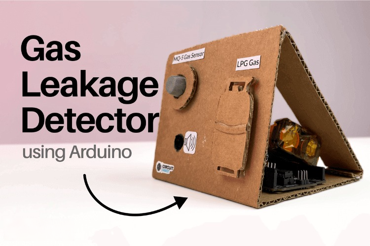
Gas Leakage Detector Using Arduino
A budget-friendly LPG gas leak detector built with an Arduino and MQ-5 gas sensor, triggering a buzzer and LED when unsafe gas levels are de...
View project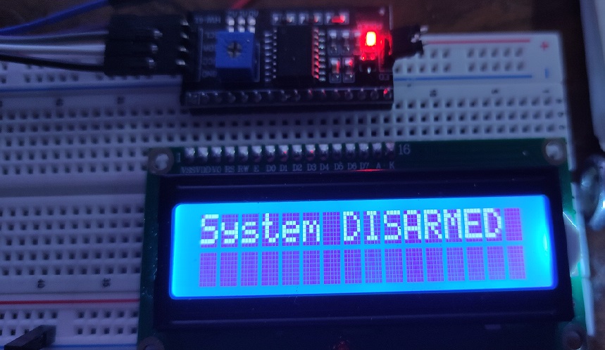
Simple Alarm System
A beginner-friendly home alarm with PIR motion sensing, keypad PIN entry, and separate entry/exit timing delays, built to be easy to expand.
View project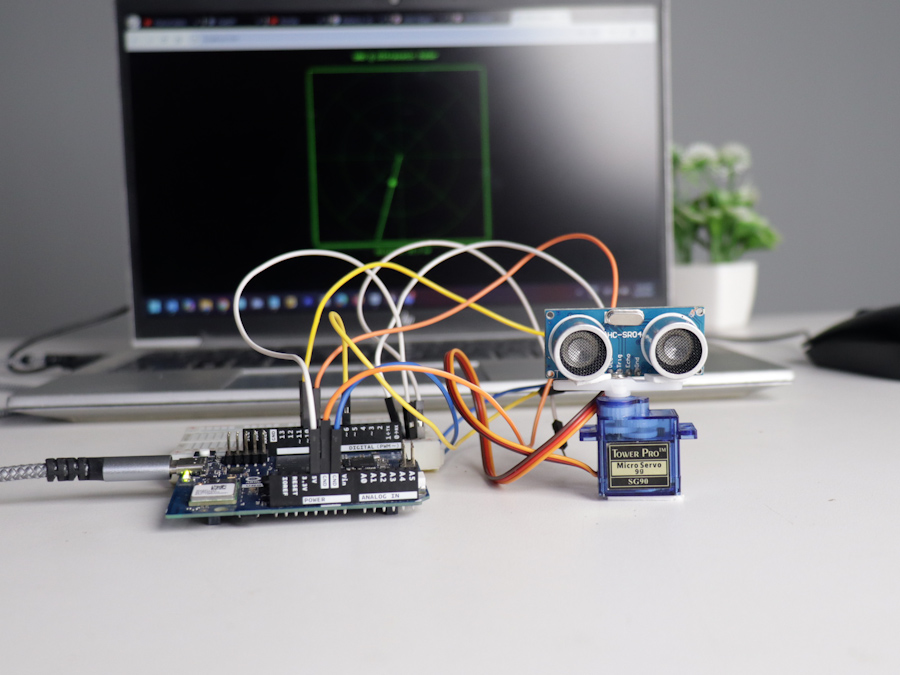
Ultrasonic Sensor Project with Arduino UNO Q
A beginner-friendly first Arduino UNO Q project: a servo-swept ultrasonic sensor that renders a live sweeping radar display in a web browser...
View project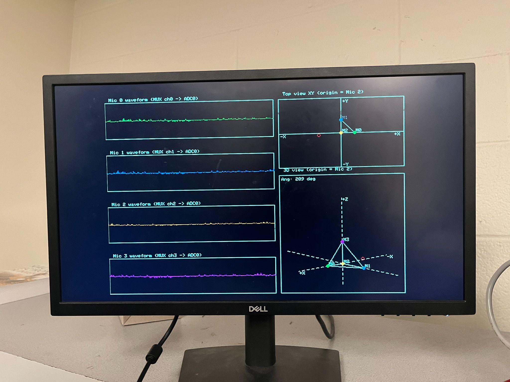
3D Audio Localization
[Fall 2025] We designed a real-time embedded system that localizes sound sources in three dimensions and visualizes them live using a four-m...
View project