Mario-Kart inspired racing game
[Fall 2022] Our final project is an arcade style racing game that is controlled using a handheld controller, inspired from mario-kart style games we played growing up.
- Suitable forB.Tech/B.E Embedded Systems students
- Build time4-6 weeks
- LevelBeginner
- Available atAjvika Labs, Kakinada
About this project
Mario-Kart Inspired Racing Game Final Project
Project Introduction
Our final project is an arcade style racing game that is controlled using a handheld controller, inspired from mario-kart style games we played growing up.
The car and the randomly curving track are displayed on a VGA screen which is connected to the controller. Both the car and track are able to horizontally wrap across the screen. As the game progresses, the track scrolls down on the screen and the player must use the controller to steer the car away from the edges of the track. Hitting the edge will result in a game over. There are also randomly generated (green “line”) markers along the track that the player needs to hit to increase their score. However, hitting a marker will also cause the game to speed up, adding more difficulty as the score increases; additionally, whenever a marker is hit, a Spotify song with increasing tempo begins playing and a vibration sensor provides tactile feedback. We decided to make this our final project because we wanted a project that was engaging, fun, and easy to play. The technical details of the project also draw heavily from what we have learned from the previous labs.
High Level Design
The inspiration for our project came from the game Mario Kart Wii. The core structure of a Mario Kart game consists of a player vehicle, the track, a lap counter, and a motion controller. We took these core ideas and did our best to implement them using the PICO and VGA screen.
The logic of our game follows a straightforward set of directions. Once the game begins, if the car ever intersects with a track boundary, the game ends. Also, if it ever encounters a marker, increase the scrolling speed and increment the score counter. This continues until the player causes a game over or if the player reaches a score of 20. After a game over, the player has the option of resetting by hitting the reset button, score is reset and a new map is generated.
The only copyrights that are relevant to our project concern the use of Spotify and using the app to play music. We registered the app through the online platform for app developers, so sharing videos of the app and the songs playing is acceptable.
Hardware/Software Trade-Offs
From a general perspective, the choice was made early on to make the project more logic and software dependent rather than hardware dependent. This involved only utilizing the minimal amount of hardware necessary to aid the movement of the car and collisions with the marker and road. As such, the only hardware components utilized were the VGA screen, IMU, and a vibration motor.
Since our initial plan included a sound and music component, the spotify route as opposed to the sound synthesis was chosen. The spotify route allowed including a larger dataset of songs and significantly reduced computational overhead. However, spotify did limit the ability to customize the music at each marker collision. We played a cool synthwave playlist that fit the vibes of our game. Ultimately, the ease of implementation, reduced computation, and reduced hardware (DAC is not necessary) made spotify the better option over the digital synthesis route.
Lastly, for the marker collision, a decision was made to only count the collision if the car’s top line with any point of the marker. This significantly lowered the collision logic for markers within the main thread, but this also made hitting markers somewhat challenging. Ultimately, this simply became embedded into our game’s natural difficulty.
Hardware Design
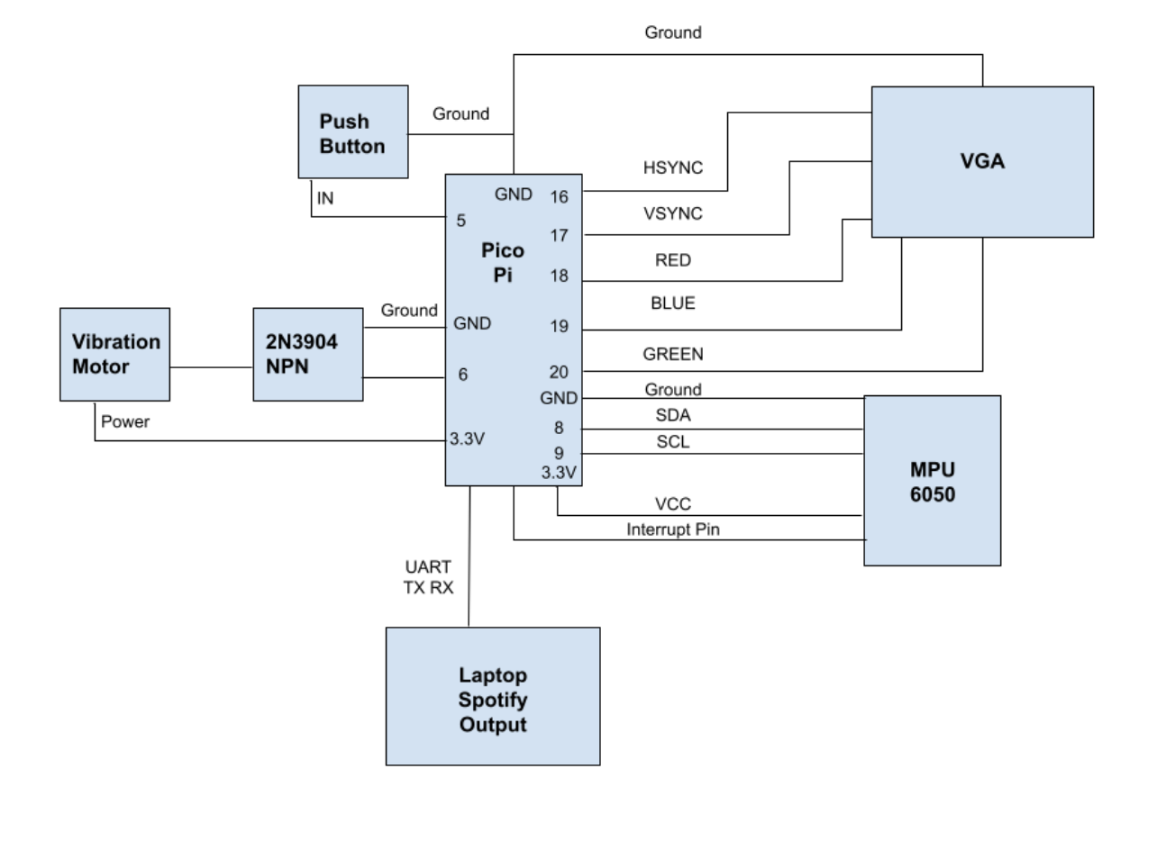
The hardware for our controller is straightforward and concise. All circuitry is done on a single breadboard and the wiring is neatly organized to avoid complications. Below we have detailed every component of the hardware as well as many diagrams and pictures of the circuitry.
1) PICO - Microcontroller in charge of running the game code, writing to the VGA screen, and taking input from the MPU-6050
2) VGA - Graphics screen that follows HSYNC and VSYNC protocol to display the track, car, and score.
3) Breadboard - 16.6 cm by 5.6 cm breadboard that holds all the hardware circuitry.
4) MPU_6050 - Gyroscope sensor attached to controller in order to measure acceleration and tilt angle. Data is used to move the vehicle on screen accordingly.
5) Vibration Motor - Used to send vibration feedback whenever the player hits a marker. Controlled using PWM.
6) 2N3904 NPN - The transistor used in the vibration motor circuitry. Allows for better control of the motor.
7) Push Button - A simple button used to start a new game or restart after a game over. It is attached to the outside of the controller.
8) Cardboard Container - A cardboard rectangular prism, approximately 18 cm by 6 cm by 5 cm. All circuitry is encapsulated by the prism. There are holes on the side to allow wires from the VGA and laptop. Can be opened and closed to allow adjustments to the breadboard.
Figure 1: Overall Hardware Setup
Figure 2: Vibration Motor Circuitry
Figure 3: 3D Model of container
Figure 4: Image of Circuit
Hardware Container
In order to provide a better user experience for the player and ensure the players safety, we wanted to put all the circuitry and breadboard wiring into a rectangular box. The player would then hold the box in one hand and use it as a remote. The original plan was to place the breadboard in a 3D printed container, but we ran out of time to print it for the demo. Instead, we used some cardboard to create a similar version of the 3D printer. This cardboard container can be opened up and closed, and has holes for all the wiring. The controller used in the demo was the cardboard container controller.
Software Design
There are three main parts to the software: main game thread, spotify thread, main
Main Game Thread: The main game thread handles the key aspects of the game including path wrapping, car-wrapping, ring-buffer updates, road and marker collision detection, core updates, and frame updates. Additionally, at each marker hit, the main thread also signals a shared spotify variable to indicate a new track switch.
Serial Spotify Thread: This thread runs on core 1 and concurrently reads the shared spotify_signal variable to recognize if a “next” (indicating switch to the next song in the queue) must be sent to the spotify script. The thread avoids race conditions by only reading the variable as opposed to also writing to it. When the game is reset, a “rese” is sent, resetting the song queue.
Main: The main handles initializing the GPIO interrupt for the IMU. This pulsed signal on the gpis pin determines when the data should be read from the IMU’s buffer. Additionally, the main also assigns the game thread to core 0 and the serial/spotify thread to core 1. Lastly, it assigns the PWM functionality to the vibration motor, setting the PWM max threshold to 12.
Software Specifics
Ring Buffer (vertical wrapping)
Vertical scrolling was pivotal to create the effect of the road moving from the top to the bottom of the screen and the car moving forward. While the trivial strategy of simply redrawing the pixels in the same location iteratively was considered, this strategy would severely limit the road’s ability to hold properties such as curvature, obstacles, power-ups, and colors, several limiting the difficulty and fun of the game.
To cycle the properties of the road down, two strategies were considered: the ring buffer and bubbling. The bubbling straggles would involve looping through the entire array and manually bubbling properties down through the entire array. This is a rather inefficient approach and would limit the amount of game logic calculations that can be be carried out. The ring buffer approach is an efficient approach that utilizes pointers to indices in the array, and rather than manually bubbling data, only the pointers are shifted by 1 per iteration. The road state pointed to by the top pointer is then update with new properties rendering a new road state at the top of the vga screen. The previous states are naturally pushed down as the road is redrawn on the vga from the new top pointer to the new bottom pointer.
The ring buffer, in this way, facilitated expanding the state properties of the road and only required a single index update per frame. The ring buffer strategy integrated rather well with the array design structure chosen initially as only two pointer had to be tracked: pointerEnd and pointerStart.
It was a little difficult to understand how the ring buffer was operating (two pointers chasing each other around a static memory space), but it was worth spending some time to understand it, as the relative performance increase due to using a ring buffer was necessary to implement functional scrolling.
Figure 5: Image of struct utilized
Road_prop is the struct that was used to keep track of all of the data associated with a particular pixel on the track. The reason for having to keep track of all of this positional state information (l_xpos, r_xpos, y_pos) for each ring buffer track element was due to the challenges of wrapping and erasing previously drawn elements. This motivation will be covered in greater detail in the wrapping description section.
An added bonus to the road_prop struct was the colorData, which enabled keeping track of the color of a particular element of the array, so we were able to generate a Mario Kart “Rainbow-Road” like effect by incrementing a counter for subsequent pixels added and changing the color when that count threshold was reached. The boundaries of the track in Figure a exhibits this behavior.
Marker Generation & Deletion
To generate markers, each road was provided a marker state. This character property effectively indicated the directional placement of the marker.
To initially generate the marker, a random value was first selected. To control the probability of the marker generation, it is only generated when when the random value is above 48 in a range of 0 to 50 inclusive. This ult
Project Introduction
Our final project is an arcade style racing game that is controlled using a handheld controller, inspired from mario-kart style games we played growing up.
The car and the randomly curving track are displayed on a VGA screen which is connected to the controller. Both the car and track are able to horizontally wrap across the screen. As the game progresses, the track scrolls down on the screen and the player must use the controller to steer the car away from the edges of the track. Hitting the edge will result in a game over. There are also randomly generated (green “line”) markers along the track that the player needs to hit to increase their score. However, hitting a marker will also cause the game to speed up, adding more difficulty as the score increases; additionally, whenever a marker is hit, a Spotify song with increasing tempo begins playing and a vibration sensor provides tactile feedback. We decided to make this our final project because we wanted a project that was engaging, fun, and easy to play. The technical details of the project also draw heavily from what we have learned from the previous labs.
High Level Design
The inspiration for our project came from the game Mario Kart Wii. The core structure of a Mario Kart game consists of a player vehicle, the track, a lap counter, and a motion controller. We took these core ideas and did our best to implement them using the PICO and VGA screen.
The logic of our game follows a straightforward set of directions. Once the game begins, if the car ever intersects with a track boundary, the game ends. Also, if it ever encounters a marker, increase the scrolling speed and increment the score counter. This continues until the player causes a game over or if the player reaches a score of 20. After a game over, the player has the option of resetting by hitting the reset button, score is reset and a new map is generated.
The only copyrights that are relevant to our project concern the use of Spotify and using the app to play music. We registered the app through the online platform for app developers, so sharing videos of the app and the songs playing is acceptable.
Hardware/Software Trade-Offs
From a general perspective, the choice was made early on to make the project more logic and software dependent rather than hardware dependent. This involved only utilizing the minimal amount of hardware necessary to aid the movement of the car and collisions with the marker and road. As such, the only hardware components utilized were the VGA screen, IMU, and a vibration motor.
Since our initial plan included a sound and music component, the spotify route as opposed to the sound synthesis was chosen. The spotify route allowed including a larger dataset of songs and significantly reduced computational overhead. However, spotify did limit the ability to customize the music at each marker collision. We played a cool synthwave playlist that fit the vibes of our game. Ultimately, the ease of implementation, reduced computation, and reduced hardware (DAC is not necessary) made spotify the better option over the digital synthesis route.
Lastly, for the marker collision, a decision was made to only count the collision if the car’s top line with any point of the marker. This significantly lowered the collision logic for markers within the main thread, but this also made hitting markers somewhat challenging. Ultimately, this simply became embedded into our game’s natural difficulty.
Hardware Design
The hardware for our controller is straightforward and concise. All circuitry is done on a single breadboard and the wiring is neatly organized to avoid complications. Below we have detailed every component of the hardware as well as many diagrams and pictures of the circuitry.
1) PICO - Microcontroller in charge of running the game code, writing to the VGA screen, and taking input from the MPU-6050
2) VGA - Graphics screen that follows HSYNC and VSYNC protocol to display the track, car, and score.
3) Breadboard - 16.6 cm by 5.6 cm breadboard that holds all the hardware circuitry.
4) MPU_6050 - Gyroscope sensor attached to controller in order to measure acceleration and tilt angle. Data is used to move the vehicle on screen accordingly.
5) Vibration Motor - Used to send vibration feedback whenever the player hits a marker. Controlled using PWM.
6) 2N3904 NPN - The transistor used in the vibration motor circuitry. Allows for better control of the motor.
7) Push Button - A simple button used to start a new game or restart after a game over. It is attached to the outside of the controller.
8) Cardboard Container - A cardboard rectangular prism, approximately 18 cm by 6 cm by 5 cm. All circuitry is encapsulated by the prism. There are holes on the side to allow wires from the VGA and laptop. Can be opened and closed to allow adjustments to the breadboard.
Figure 1: Overall Hardware Setup
Figure 2: Vibration Motor Circuitry
Figure 3: 3D Model of container
Figure 4: Image of Circuit
Hardware Container
In order to provide a better user experience for the player and ensure the players safety, we wanted to put all the circuitry and breadboard wiring into a rectangular box. The player would then hold the box in one hand and use it as a remote. The original plan was to place the breadboard in a 3D printed container, but we ran out of time to print it for the demo. Instead, we used some cardboard to create a similar version of the 3D printer. This cardboard container can be opened up and closed, and has holes for all the wiring. The controller used in the demo was the cardboard container controller.
Software Design
There are three main parts to the software: main game thread, spotify thread, main
Main Game Thread: The main game thread handles the key aspects of the game including path wrapping, car-wrapping, ring-buffer updates, road and marker collision detection, core updates, and frame updates. Additionally, at each marker hit, the main thread also signals a shared spotify variable to indicate a new track switch.
Serial Spotify Thread: This thread runs on core 1 and concurrently reads the shared spotify_signal variable to recognize if a “next” (indicating switch to the next song in the queue) must be sent to the spotify script. The thread avoids race conditions by only reading the variable as opposed to also writing to it. When the game is reset, a “rese” is sent, resetting the song queue.
Main: The main handles initializing the GPIO interrupt for the IMU. This pulsed signal on the gpis pin determines when the data should be read from the IMU’s buffer. Additionally, the main also assigns the game thread to core 0 and the serial/spotify thread to core 1. Lastly, it assigns the PWM functionality to the vibration motor, setting the PWM max threshold to 12.
Software Specifics
Ring Buffer (vertical wrapping)
Vertical scrolling was pivotal to create the effect of the road moving from the top to the bottom of the screen and the car moving forward. While the trivial strategy of simply redrawing the pixels in the same location iteratively was considered, this strategy would severely limit the road’s ability to hold properties such as curvature, obstacles, power-ups, and colors, several limiting the difficulty and fun of the game.
To cycle the properties of the road down, two strategies were considered: the ring buffer and bubbling. The bubbling straggles would involve looping through the entire array and manually bubbling properties down through the entire array. This is a rather inefficient approach and would limit the amount of game logic calculations that can be be carried out. The ring buffer approach is an efficient approach that utilizes pointers to indices in the array, and rather than manually bubbling data, only the pointers are shifted by 1 per iteration. The road state pointed to by the top pointer is then update with new properties rendering a new road state at the top of the vga screen. The previous states are naturally pushed down as the road is redrawn on the vga from the new top pointer to the new bottom pointer.
The ring buffer, in this way, facilitated expanding the state properties of the road and only required a single index update per frame. The ring buffer strategy integrated rather well with the array design structure chosen initially as only two pointer had to be tracked: pointerEnd and pointerStart.
It was a little difficult to understand how the ring buffer was operating (two pointers chasing each other around a static memory space), but it was worth spending some time to understand it, as the relative performance increase due to using a ring buffer was necessary to implement functional scrolling.
Figure 5: Image of struct utilized
Road_prop is the struct that was used to keep track of all of the data associated with a particular pixel on the track. The reason for having to keep track of all of this positional state information (l_xpos, r_xpos, y_pos) for each ring buffer track element was due to the challenges of wrapping and erasing previously drawn elements. This motivation will be covered in greater detail in the wrapping description section.
An added bonus to the road_prop struct was the colorData, which enabled keeping track of the color of a particular element of the array, so we were able to generate a Mario Kart “Rainbow-Road” like effect by incrementing a counter for subsequent pixels added and changing the color when that count threshold was reached. The boundaries of the track in Figure a exhibits this behavior.
Marker Generation & Deletion
To generate markers, each road was provided a marker state. This character property effectively indicated the directional placement of the marker.
To initially generate the marker, a random value was first selected. To control the probability of the marker generation, it is only generated when when the random value is above 48 in a range of 0 to 50 inclusive. This ult
Technologies used
Hardware components
- IMU
- gyroscope
- DAC
Software & tools
- C
- Arduino IDE
Project demo video
What you get
- Working project / hardware kit, tested before delivery
- Complete source code with explanation
- Project demo and guidance for your viva
- Project report, PPT and IEEE paper support (on request)
Delivery & Payment
Delivery takes a minimum of two weeks from the date your inquiry is confirmed.
Payment is in two parts:
• 50% advance to start the project
• Remaining 50% before delivery
Note:
• Documentation and PPT are not included by default
• If you need documentation/PPT, it can be arranged for extra time and cost
We'll confirm the exact timeline and cost with you after reviewing your requirements.
Related Embedded Systems projects

Embedded Systems
Gas Leakage Detector Using Arduino
A budget-friendly LPG gas leak detector built with an Arduino and MQ-5 gas sensor, triggering a buzzer and LED when unsafe gas levels are de...
View project
Embedded Systems
Simple Alarm System
A beginner-friendly home alarm with PIR motion sensing, keypad PIN entry, and separate entry/exit timing delays, built to be easy to expand.
View project
Embedded Systems
Ultrasonic Sensor Project with Arduino UNO Q
A beginner-friendly first Arduino UNO Q project: a servo-swept ultrasonic sensor that renders a live sweeping radar display in a web browser...
View project
Embedded Systems
3D Audio Localization
[Fall 2025] We designed a real-time embedded system that localizes sound sources in three dimensions and visualizes them live using a four-m...
View project