MacroData refinement
[Spring 2025] A Severance-inspired MacroData Refinement implementation where numbers are sorted based on emotions (Woe, Frolic, Dread, and Malice) they evoke. Built on Raspberry Pi Pico.
- Suitable forB.Tech/B.E Embedded Systems students
- Build time4-6 weeks
- LevelIntermediate
- Available atAjvika Labs, Kakinada
About this project
ECE 4760 Final Report
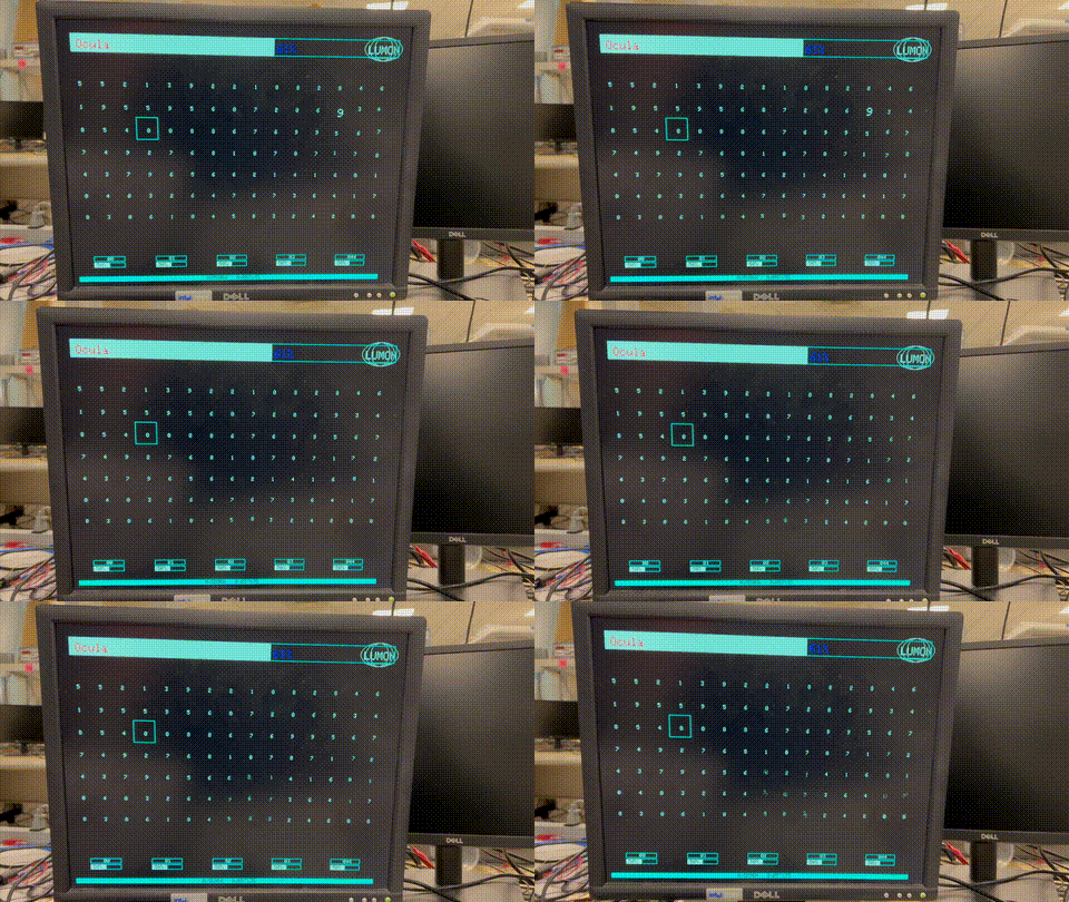
Figure 1: Game Demo showing quivering numbers.
We recreated the mysterious MacroData Refinement game from Severance on a Raspberry Pi
Pico, complete with
VGA display and joystick controls
Introduction
This project implements an interactive game simulating the MacroData Refinement (MDR) process from the Apple
TV+ show
Severance, rendered on a VGA display and controlled via a joystick and button interfaced with a Raspberry Pi
Pico
(RP2040). We developed this game to explore the themes presented in the show, such as corporate control and the
nature
of work, by allowing players to experience a version of the mysterious task of "refining" data, while also
serving as a
platform to implement real-time graphics, animation, and microcontroller-based game logic.
High level design
The primary inspiration for this
project was the television series Severance. A central element of the show is Lumon
Industries' Macro Data Refinement department, where "severed" employees sort groups of numbers based on the
emotions
(Woe, Frolic, Dread, and Malice) these numbers evoke. The "terminal-looking" interface provided a compelling
basis for
an interactive game. We also drew inspiration from the fan-made web version of the game available at
lumon-industries.com, aiming to create a hardware-based counterpart. The project's goal was to not only
replicate the
game mechanics but also to weave in "easter eggs" and the general aesthetic of the show.
We utilized fixed-point
arithmetic for efficient computation, particularly within the boid animation and game logic
updates. We used 16.15 fixed-point numbers for calculations involving boid positions, velocities, and
behavioral
parameters. This allowed us to cram heavy floating point computations into the game logic and still meet
frame rate
deadlines without sacrificing smooth animations. Additionally, besides computing positions of pixels on the
screen, much
of the math in this game came from the movement of the invisible "boids" that cause numbers to quiver. This
movement is
governed by a flocking algorithm which causes each boid to adjust its velocity based on factors such as:
cohesion
(moving towards the average position of nearby boids), separation (avoiding really close by boids) and wall
avoidance
(turn away from screen boundaries). More parameters such as VISUAL_RANGE, PROTECTED_RANGE control the
specifics of these
behaviors and distance calculations were approximated using the "Alpha max plus beta min" method.
The game operates using a state machine and concurrent processing handled by
protothreads.
Game States:
The game progresses through three states defined by the
PlayState
enum:
The game begins in the
START_SCREEN
state, which displays an initial message prompting the user
to
start. During the
PLAYING
state, which is the main interactive phase, the refinement process
takes
place. Finally, when all refining is complete, the game transitions to the
GAME_WON
state where
it
displays the completion screen.
Main loop:
Within the
PLAYING
state, the system continuously.
It updates boid positions and velocities, checks for collisions between boids and the
number grid (which triggers animations), and scans for user input through the joystick for cursor movement
and
button for refinement. When refinement is triggered on a "bad number", the game state is updated by removing
refined numbers and regenerating new ones, bin animations are triggered, and the overall progress bar is
updated. Finally, all visual elements are redrawn on the VGA screen.
Protothreads:
Concurrency is managed using the
pt_cornell_rp2040_v1_3.h
library.
On Core 0, we have three protothreads: protothread_graphics which handles drawing the main game screen,
protothread_joystick which reads ADC values from the joystick and updates cursor position, and
protothread_button_press which debounces the refinement button and triggers refinement logic. Core 1 runs
two
protothreads: protothread_graphics_too which manages the animations of the Woe, Frolic, Dread, and Malice
bins,
and protothread_progress_bar which updates the state of the main progress bar animation.
All the game code is written in C. We utilized the provided
vga library
which gave
us a great head start. An Analog
joystick (purchased from Amazon) was chosen for user interaction. The proposal initially considered eight
buttons, but a
joystick for cursor movement was found to be more intuitive for navigating the grid.
Existing Patents, Copyrights, and Trademarks
This project is directly inspired by the Severance television show and related imagery from Lumon Industries,
which are
intellectual property of Apple Inc. and/or the show's creators. Our project is intended solely for educational
and
non-commercial purposes within the context of ECE 4760. We do not claim ownership of any copyrighted or
trademarked
material from Severance. The game mechanics, while inspired by the show, are our own faithful interpretation and
implementation.
Program/Hardware design
Figure 2: Physical Hardware.
Joystick
For the hardware of the joystick, we connected it to the program using the Analog to Digital Converter (ADC)
feature
on the Raspberry Pi. This was implemented in a single protothread called
Protothread_joystick
. We
reserved GPIO
pins
27 and 28 to function as the Voltage-Read-X-coordinate (
VRX
) and Voltage-Read-Y-coordinate
(
VRY
), respectively.
To
implement the joystick correctly, we must first understand how this specific joystick works.
Figure 3: Image of Joystick used in project and its respective wiring
Moving the joystick left or right changes the voltage of the
VRX
whereas up and down changes the
voltage of
VRY
This movement relays the analog voltage level to the RP2040 to which it then converts to a binary signal. In
order
to provide voltage in the first place, we connect the joystick to GPIO pin 36, which functions as an output of
3.3
Volts.
When turned left, the voltage level is 0 (shorted to ground), corresponding to a binary value of 0. Similarly,
when
turned right, the voltage level is 3.3 volts and that corresponds to a binary value of 8023. Generally in
joystick
architecture that is found in any controller, there is a threshold for which when the ADC value crosses, it
counts
as a read for turning left or right, For example, our int value
X_RIGHT_THRESHOLD
is set to 3000,
for when the
returned ADC value is greater than this number the program knows to count that as a right. This is also done for
left, up and down.
Our first attempt to implement the joystick came with a small obstacle. We generally use the ADC to poll
something
such as a potentiometer, which provides a single voltage output into the RP2040. However, we are now trying to
read
two values, that being
VRX
and
VRY
. At first, we implemented an in-built feature of
the ADC known as
adc_set_round_robin
. Which uses a queue in order to have a First-in-First-out data structure. The
ADC reads one
input, puts it in the queue, and then polls the next input into the queue. However, we noticed that it randomly
picked an input to start the queue, which made it difficult to program other functions that rely on knowing if
VRX
or
VRY
is going to pop from the queue. Also, with the round robin method it provided a lot of
memory overhead,
something we were trying to avoid.
This then led to us having helper functions that when called, switched the input to be read to either VRX or
VRY.
While this does increase our running time a bit, it was the best option as we favored memory over speed.
The ADC feature polls the voltage level of the joystick far too frequently for any realistic human interaction.
In
order to circumvent this, we added a timer that polls the protothread every 70 ms. We got to this number by user
testing random numbers and saw which timer gave us the most smooth interaction.
Included in the joystick is a button that can be pressed. This means we need debouncing and implies that there
should be a separate protothread. This is done because debouncing relies on quick execution of a state machine
that
tells us if it reads a button press because a person is pressing the button or contact between mechanical
switches
that can happen arbitrarily. We need to read this at a higher frequency than that of the joystick. So we
schedule
the protothread for the button to run every 30 ms as opposed to the 70 ms the joystick protothread runs on.
Figure 4: Debouncing State Machine
VGA Display
To support the VGA display, specific GPIO pins on the RP2040 are connected to the VGA port:
GPIO 16
is used for
horizontal sync (Hsync), and
GPIO 17
for vertical sync (Vsync). Color signals are sent through
GPIO 18
and
GPIO 19
for
green (via 470 Ω and 330 Ω resistors, respectively),
GPIO 20
for blue (330 Ω), and
GPIO 21
for red (330 Ω). The
ground of the RP2040 is connected to VGA ground. The DMA channel, paced by the
DREQ_PIO0_TX2
data
request
signal,
feeds
Technologies used
Hardware components
- RP2040
- VGA display
- IMU
- ADC
- relay
Software & tools
- C
- Arduino IDE
Project demo video
What you get
- Working project / hardware kit, tested before delivery
- Complete source code with explanation
- Project demo and guidance for your viva
- Project report, PPT and IEEE paper support (on request)
Related Embedded Systems projects
Gas Leakage Detector Using Arduino
A budget-friendly LPG gas leak detector built with an Arduino and MQ-5 gas sensor, triggering a buzzer and LED when unsafe gas levels are de...
View project
Simple Alarm System
A beginner-friendly home alarm with PIR motion sensing, keypad PIN entry, and separate entry/exit timing delays, built to be easy to expand.
View project
Ultrasonic Sensor Project with Arduino UNO Q
A beginner-friendly first Arduino UNO Q project: a servo-swept ultrasonic sensor that renders a live sweeping radar display in a web browser...
View project
3D Audio Localization
[Fall 2025] We designed a real-time embedded system that localizes sound sources in three dimensions and visualizes them live using a four-m...
View project