Handwriting digit detector
[Spring 2025] A memory-optimized CNN running on the RP2040 microcontroller classifies handwritten digits drawn on a resistive touchscreen, showcasing real-time inference despite stringent memory constraints.
- Suitable forB.Tech/B.E Embedded Systems students
- Build time4-6 weeks
- LevelBeginner
- Available atAjvika Labs, Kakinada
About this project
Introduction
The core of this project revolves around deploying a Convolutional Neural Network (CNN) on the RP2040
microcontroller to classify handwritten digits. The CNN is structured with quantized 8-bit integer weights
and activations to fit within the limited RAM of the RP2040 while maintaining a reasonable inference speed.
Input data is collected via a resistive touchscreen, which functions as a crude drawing interface. The touchscreen
readings are processed and mapped into a 28x28 pixel grid, which serves as input to the CNN. After classification,
the predicted digit is displayed on an OLED screen, providing immediate feedback to the user.
upload video to youtube & embed
High Level Design
Rationale
Over the course of the semester, we found Lab 2: Digital Galton Board to be the most compelling project.
This lab pushed the memory limits of the RP2040 by requiring extensive optimization to fit a complex physics
simulation within the microcontroller’s limited RAM memory. We managed to incorporate
as many simulated balls as possible, optimizing both data structures and code implementation. This experience
inspired us to further explore the RP2040’s capabilities under stringent memory constraints, leading to the idea
of implementing TinyML on the same hardware platform. Given that machine learning models are traditionally
memory-intensive, we aimed to investigate how effectively we could fit a functional CNN onto the RP2040 while
maintaining real-time inference performance. This challenge of pushing the RP2040’s limits formed the core
motivation for our final project.
Background
Resistive touchscreen
The input to the CNN is taken in from a resistive touchscreen.
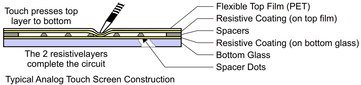
A resistive touchscreen operates based on the principles of a voltage divider network formed by two conductive layers
separated by a small gap. When a user applies pressure to the touchscreen surface, the two conductive layers make contact,
creating a variable resistor network. By selectively configuring certain pins as inputs and outputs, we can effectively
measure the X and Y coordinates of the touch event.
Basics of Resistive Touchscreen Construction, from Professor Hunter Adam's Resistive Touchscreen Demo
In this project, we began by using a baseline demo code provided by Professor Hunter Adams, which was designed to map
the touchscreen readings to VGA output. This code serves as a foundational structure for our data acquisition process.
The resistive touchscreen consists of four terminals:
X+, X-, Y+, Y-
. To accurately read both X and Y coordinates, we
alternate between two pin configurations:
Reading the Y Coordinate:
The X+ and X- pins are configured as outputs, set to
HIGH
and
LOW
respectively, forming a voltage divider network along the X-axis.
The Y+ and Y- pins are configured as inputs, allowing the ADC to sample the Y-axis voltage based on the current X-axis configuration.
Reading the X Coordinate:
The Y+ and Y- pins are configured as outputs, set to
HIGH
and
LOW
respectively, forming a voltage divider network along the Y-axis.
The X+ and X- pins are configured as inputs, allowing the ADC to sample the X-axis voltage based on the current Y-axis configuration.
Analog-Digital Converter:
The RP2040’s ADC module is a 12-bit successive approximation ADC that reads voltages
ranging from 0V to 3.3V and converts them to a 12-bit integer value. In our implementation,
we read the X and Y voltages by configuring the ADC to sample from GPIO pins
GP26: ADC0
and
GP27: ADC1
To mitigate noise and provide a more stable reading, a simple low-pass filter is implemented
using a 16-sample buffer. The raw ADC readings for each axis are accumulated and averaged to provide a smoothed output. This averaging is extremely important for stabilizing
the output values, given that the resistive touchscreen readings fluctuate due to contact resistance variability. The details and challenges of our resistive touchscreen implementation are expanded upon in Hardware Design.
Timer Interrupt Service Routine:
To constantly sample the current position on the resistive touchscreen, a timer interrupt service routine (ISR) runs at a fixed 250Hz frequency, toggling between the X and Y measurement modes.
This sampling rate was specifically chosen to ensure that X and Y readings were not coupled, while also allowing
rapid touch events to be accurately captured and processed.
The ISR performs the following steps:
Switch to the next measurement mode (X or Y).
Read the ADC value for the current axis.
Update the 16-sample buffer.
Compute the average value and store it as the current coordinate reading.
This methodology effectively decouples the sampling process from the main application logic, allowing the touchscreen data acquisition to run independently without
blocking the primary control loop. This ensures that even during classification or display operations, the touchscreen data acquisition continues uninterrupted, maintaining
consistent data availability. The final scaled X, Y values are mapped to a 28x28 grid, serving as input data to the CNN model.
Convolutional Neural Network
The CNN model was developed and trained in Python using the TensorFlow library. The training dataset used was the MNIST dataset, a widely recognized dataset of 28x28 grayscale
images representing handwritten digits ranging from 0 to 9. The goal was to train a lightweight, memory-efficient CNN model that could be quantized and deployed to the RP2040 microcontroller
without exceeding its limited RAM capacity.
Dataset Preperation:
The dataset utilized for training the CNN model was the MNIST dataset, which consists of 60,000 training images and 10,000 testing images of
handwritten digits ranging from 0 to 9. Each image is a grayscale 28x28 pixel matrix.
The dataset was imported using TensorFlow’s built-in
mnist.load_data()
function, which returns both the training and testing datasets as
(x_train, y_train)
and
(x_test, y_test)
tuples. These datasets contain the raw pixel values in the range [0, 255].
Since the CNN expects a 4D tensor input
(batch_size, height, width, channels)
, the images were reshaped to include a single channel dimension to indicate that the images are grayscale.
Model Architecture:
The model consists of a series of convolutional and max-pooling layers to extract spatial features from the 28x28 input images. The initial convolutional layers utilize small 3x3 kernels to capture fine-grained edge
and texture information, followed by max-pooling to reduce spatial dimensions and retain key features. A fully connected dense layer aggregates the extracted features, and a final dense layer with softmax activation outputs the classification probabilities
for each of the ten digit classes.
Layer
Function
Input Shape
Output Shape
Conv2D
Extracts low-level features (edges, corners). Helps identify basic shapes in the digit input.
(1, 28, 28, 1)
(1, 26, 26, 8)
MaxPooling2D
Reduces spatial dimensions, downsampling to keep the RP2040’s RAM use low. Provides translation invariance, important for touchscreen inputs.
(1, 26, 26, 8)
(1, 13, 13, 8)
Conv2D
Extracts higher-level features. Adds additional filters to detect more complex patterns in the digit strokes.
(1, 13, 13, 8)
(1, 11, 11, 16)
MaxPooling2D
Further reduces spatial dimensions and enhances robustness to spatial variations.
(1, 11, 11, 16)
(1, 5, 5, 16)
Flatten
Converts 3D feature maps to a 1D vector for the dense layers. Prepares data for classification.
(1, 5, 5, 16)
(1, 400)
Dense
Fully connected layer that aggregates spatial features into meaningful patterns for classification. ReLU keeps activations sparse, lowering MAC count during inference.
(1, 400)
(1, 64)
Dense
Output layer with softmax activation, providing classification probabilities for each digit (0-9).
(1, 64)
(1, 10)
Before quantization, the total model occupies 107.6 KB of memory.
Training and Evaluation:
The model was compiled using the Adam optimizer and trained for 5 epochs using a sparse categorical cross-entropy loss function.
The training accuracy improved steadily across epochs, achieving a final accuracy of approximately 98.9% on the test dataset.
Quantization and TFLite:
After training, the model was converted to TensorFlow Lite format for deployment on the RP2040. The conversion included full integer quantization to reduce
model size and memory footprint to 56 KB.
The choice of model architecture, along with how it interfaces with the RP2040 is further explained in Software Design.
Logical Structure
The system is structured as a three-stage pipeline consisting of data acquisition, processing, and inference.
Data Acquisition:
The resistive touchscreen is sampled at a fixed frequency using a timer ISR. The ISR captures X and Y coordinates alternately, filters the data using a 16-sample averaging buffer, and maps the coordinates to a 28x28 pixel grid.
Data Processing:
The pixel grid is preprocessed to ensure consistency in scaling and orientation. Preprocessing also involves padding the drawn image with grey pixels to create a thicker stroke for better edge detection. The 28x28 grid is then fed to the CNN.
Inference:
The CNN processes the input data and outputs a probability vector of ten values, each representing a predicted digit (0-9). The highest probability class is selected and displayed on the OLED screen. Additionally, feedback is provided to the user through LED
indicators and button-based controls.
Software / Hardware Tradeoffs
The primary hardware trade-off centered around the choice between a resistive touch
Technologies used
Hardware components
- RP2040
- IMU
- ADC
Software & tools
- Python
Project demo video
What you get
- Working project / hardware kit, tested before delivery
- Complete source code with explanation
- Project demo and guidance for your viva
- Project report, PPT and IEEE paper support (on request)
Related Embedded Systems projects

Gas Leakage Detector Using Arduino
A budget-friendly LPG gas leak detector built with an Arduino and MQ-5 gas sensor, triggering a buzzer and LED when unsafe gas levels are de...
View project
Simple Alarm System
A beginner-friendly home alarm with PIR motion sensing, keypad PIN entry, and separate entry/exit timing delays, built to be easy to expand.
View project
Ultrasonic Sensor Project with Arduino UNO Q
A beginner-friendly first Arduino UNO Q project: a servo-swept ultrasonic sensor that renders a live sweeping radar display in a web browser...
View project
3D Audio Localization
[Fall 2025] We designed a real-time embedded system that localizes sound sources in three dimensions and visualizes them live using a four-m...
View project