Hand conductor
This baton conducts both electricity and an electronic orchestra; based on the speed at which you signal a 4/4 measure, the corresponding audio playback and visualizer will match your rhythm.
- Suitable forB.Tech/B.E Embedded Systems students
- Build time4-6 weeks
- LevelIntermediate
- Available atAjvika Labs, Kakinada
About this project
High Level Design
Program/Hardware Design
Results
Conclusion
Appendix
ECE 4760 Final Project:
Hand Conductor
Introduction
Test your rhythm skills with our rendition of a conductor baton! This baton conducts both electricity and an electronic orchestra; based on the speed at which you signal a 4/4 measure, the corresponding audio playback and visualizer will match your rhythm. The music and animation play at the beats per minute you have marked, and will pause completely if the baton stops moving.
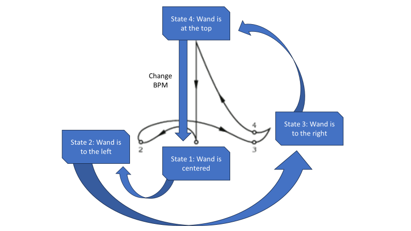
In order to make this project, we have used two Raspberry Pi PicoW where one acts as the central station and the other as the peripheral. The central PicoW acts as the UDP access point and controls the audio output and VGA animation through direct memory access and SPI communication based on the desired output rate. The peripheral PicoW is attached to a 3D printed baton which houses an IMU to periodically detect gyroscope motion with I2C communication and a battery pack. The peripheral PicoW uses the IMU and a finite state machine to calculate the motioned beats per minute and paused/unpaused state and sends the information wirelessly to the central PicoW. The following diagram depicts how the motions of the baton in a 4/4 time signature correspond to changes in the FSM state.
High Level Design
Rationale and sources of your project idea
Our project takes inspiration from a conductor baton, which allows a conductor to communicate tempo and pauses with the rest of the orchestra depending on the gestured motions. Since previous ECE 4760 labs discussed the use of the audio output, VGA screen, and IMU data, it was convenient to build from Labs 1-3.
Background math
Our device plays back audio using a DMA channel to transfer audio data from flash memory to the DAC. Most .wav files have a default sampling rate of 44.1 kHz, and as such the timer to trigger this DMA channel has a frequency of 44.1 kHz. We modulate the audio playback speed by increasing or decreasing the frequency of the audio DMA channel timer. This is achieved by the following line of code:
dma_factor = (125000000 / Fs) * (WAV_BPM / bpm) ;
Where 125000000 represents the 125 MHz internal clock timer of the RP2040 microcontroller, Fs represents a base audio sample rate of 44.1 kHz, WAV_BPM represents the base bpm of the song and bpm represents the desired bpm. The DMA timer fraction is then set to a value of 1 / dma_factor. The numerical value of (125000000 / Fs) represents the factor necessary to achieve a DMA clock speed of 44.1 kHz. Then the ratio of (((float) WAV_BPM) / ((float) bpm)) is used to scale up or down the factor we are dividing the DMA clock by. For example, to double the bpm from the initial song bpm, we want to double the frequency of the audio playback. This is achieved by doubling the DMA clock frequency, by halving the value of dma_factor.
Logical structure
Our two PicoW have the following protothreads running on each core:
The following highlights a simplified logic overview:
Program/Hardware Design
Program details
The central PicoW program can be divided into three main subsystems. The first role of the central PicoW is to output audio data to the DAC, and eventually a speaker further downstream. Approximately 12 seconds of 44.1 kHz, mono audio data approximating to 1 MB is stored on the PicoW flash memory, which can store a maximum of 2 MB. This audio data is formatted as a preprocessed array constructed via a python script, that automatically converts a 16-bit wav file into a c array of 12-bit values (the maximum resolution of the DAC) by removing the .wav header and performing some bitwise arithmetic. The data is streamed directly from flash memory to the PicoW’s SPI output which corresponds to the input of the DAC. This is achieved using a combination of two DMA channels, labeled control and data. The data DMA channel operates at 44.1 kHZ and iterates through the flash memory array, sending each value to the DAC. The data channel is chained to the control channel, which then resets the read address of the data channel back to the 0th index of the .wav array.
The second role of the central PicoW is to draw a colorful animation on the VGA screen, which is done on core 1 of the microcontroller. The VGA interfacing code was built off of the examples provided by Professor Adams. One animation drawn by the PicoW is an audio visualizer that represents the raw audio values being sent to the DAC. The exact audio values are stored by the DMA value register and plotted as a graph, with the x-axis representing time and the y-axis representing the audio value. A second animation is drawn using a timer interrupt on core 1 to pulsate at the same timing as the song’s BPM. This is done by precisely setting the timer interrupt to occur at an exact fraction of the period of each beat. For example, since the animation consists of 12 circles of an increasing radius, we set the period of the timer interrupt to be exactly 1/12 of the beat period. Thus, at every beat, the animation will complete one full cycle. The last VGA drawing consists of drawing text on the screen that displays the current BPM and song name.
The rest of the central PicoW functionality occurs on a series of threads scheduled on core 0. First, two threads correspond to sending and receiving data through UDP communication with the peripheral PicoW. A third thread is used for serial communication with the computer, which was mainly utilized for debugging purposes by manually setting variables. A fourth thread is used to check for updates in the BPM and pausing variables. A change in BPM is handled by changing the timer frequency corresponding to the audio data DMA channel. A decrease in BPM corresponds to a slower timer frequency, decreasing the DMA transfer rate and thus slowing down the audio playback accordingly. A pause is handled by aborting the audio data DMA channel, and re-enabling it when the pause is complete. A final thread on core 0 is used to blink the on-board LED, indicating a steady connection with the peripheral PicoW.
The peripheral PicoW has two jobs, one of which is to interpret IMU data into a conductor’s baton motions, and the second of which is to send command signals to the central PicoW over UDP. In order to read from the IMU, a PWM channel is used to trigger a timer interrupt that calls for new readings to be read from the IMU. The PicoW communicates with the IMU over I2C protocol to read accelerometer and gyroscope readings along three axes - this code was taken directly from Professor Adam’s MPU6050 demo code. Next, a thread on core 1 comprises a state machine that is triggered by the IMU’s gyroscope yaw or pitch readings. When the gyroscope’s yaw or pitch exceeds a certain threshold, the PicoW knows that the user is moving the conductor’s baton. The four states of the state machine correspond to the four motions a conductor must perform to demonstrate one full musical measure (assuming 4/4 timing). On the state transition from the 4th to the 1st beat, a new BPM is calculated based on the time spent in the state machine. This thread also checks for when the IMU reads no motion over five seconds, at which point a pause is started.
The second job of the peripheral PicoW is to send UDP packets to the central PicoW, which is done in core 0 of the microcontroller. A new packet is sent whenever there is a change in the BPM or pause variables. When this trigger occurs, a UDP send command thread is spawned. On top of the aforementioned threads, the peripheral PicoW also features debugging serial functionality to print current variable values as well as a thread to blink an LED when wireless communication is achieved.
Hardware details
Raspberry Pi PicoW Pinout:
Central PicoW Hardware:
UDP:
RP2040 GPIO 2 → RP2040 3V3(OUT)
Serial:
RP2040 GPIO 0 → UART RX (white)
RP2040 GPIO 1 → UART TX (green)
RP 2040 GND → UART GND
VGA Screen:
RP2040 GPIO 16 → VGA Hsync
RP2040 GPIO 17 → VGA Vsync
RP2040 GPIO 18 → 330 ohm resistor → VGA Red
RP2040 GPIO 19 → 330 ohm resistor → VGA Green
RP2040 GPIO 20 → 330 ohm resistor → VGA Blue
RP2040 GND → VGA GND
Reset button:
RP2040 RUN → Button Pin 1
RP2040 GND → Button Pin 2
DAC (
MCP4802 Datasheet
):
RP2040 GPIO 5 → DAC Chip Select
RP2040 GPIO 6 → DAC SCK
RP2040 GPIO 7 → DAC SDI
RP2040 3V3(OUT) → DAC VDD
RP2040 GND → DAC GND
RP2040 GND → DAC LDAC
Audio Jack (
SJ1-355XNG Datasheet
):
DAC VOUTA → Audio Jack Tip & Ring
RP2040 GND → Audio Jack Sleeve
Peripheral PicoW Hardware:
Battery Pack:
RP2040 VBUS → + Battery Pack Terminal
RP2040 GND → - Battery Pack Terminal
IMU (
MPU6050 Datasheet Link
):
RP2040 3V3(OUT) → IMU VIN
RP2040 GPIO 8 → IMU SDA
RP2040 GPIO 9 → IMU SCL
RP2040 GND → IMU GND
Referenced code
Since much of the inspiration for this project came from ECE 4760 Microcontrollers labs, much of the reference design and code came from V. Hunter Adams’ Hunter-Adams-RP2040-Demos, which is based on examples from Raspberry Pi Co. The relevant sections include Audio, PWM, Sensors, and VGA_Graphics to aid in the design of our DAC/DMA audio output, PWM output, IMU usage, VGA graphics, and UART communication.
The UDP code was referenced from Bruce Land’s Symmetrical UDP send/receive from PicoW to PicoW example. Note: this example is a modified form from Pico examples and LWIP TCP/IP contribution apps. Relevant copyrights and credits include Cornell University, Andrew McDonnell, Stephan Linz, Adam Dunkels and other maintainers of the software.
Additionally, all examples use the Protothreads library which was written by Adam Dunkels.
Things that didn't work
A functionality we attempted and tried to implement was to modulate the volume of the audio playback based on the intensity of the user’s baton motions. In order to do so, a volume amplitude variable was calculated based on the average motion detected by the IMU across one full cycle of
Technologies used
Hardware components
- RP2040
- Raspberry Pi Pico
- IMU
- MPU6050
- gyroscope
- accelerometer
- speaker
- DAC
Software & tools
- Python
Project demo video
What you get
- Working project / hardware kit, tested before delivery
- Complete source code with explanation
- Project demo and guidance for your viva
- Project report, PPT and IEEE paper support (on request)
Related Embedded Systems projects

Gas Leakage Detector Using Arduino
A budget-friendly LPG gas leak detector built with an Arduino and MQ-5 gas sensor, triggering a buzzer and LED when unsafe gas levels are de...
View project
Simple Alarm System
A beginner-friendly home alarm with PIR motion sensing, keypad PIN entry, and separate entry/exit timing delays, built to be easy to expand.
View project
Ultrasonic Sensor Project with Arduino UNO Q
A beginner-friendly first Arduino UNO Q project: a servo-swept ultrasonic sensor that renders a live sweeping radar display in a web browser...
View project
3D Audio Localization
[Fall 2025] We designed a real-time embedded system that localizes sound sources in three dimensions and visualizes them live using a four-m...
View project