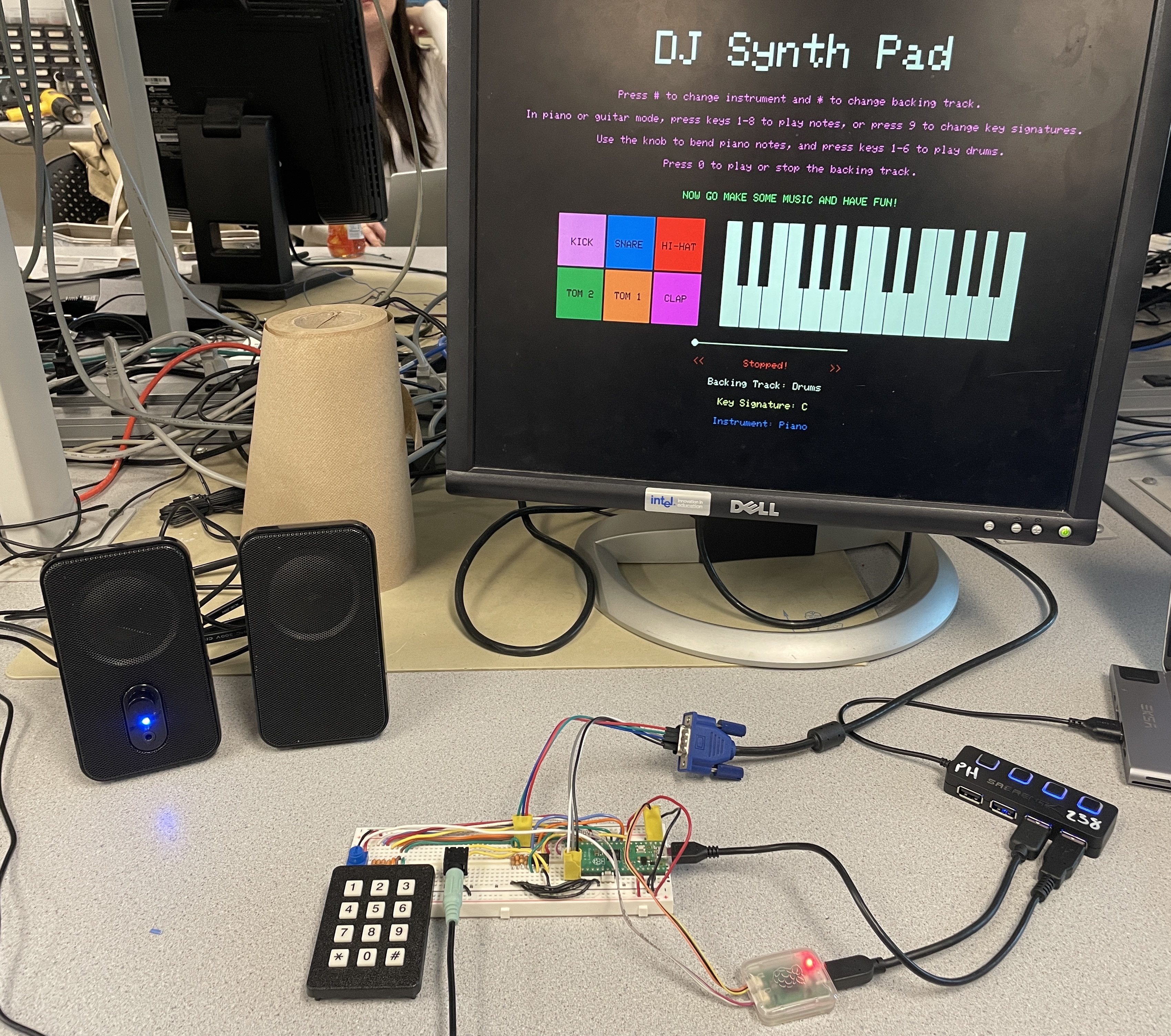
DJ synth pad
[Spring 2025] DJ Synth Pad: ECE 5730 Final Project
- Suitable forB.Tech/B.E Embedded Systems students
- Build time4-6 weeks
- LevelAdvanced
- Available atAjvika Labs, Kakinada
About this project
Project Introduction
High Level Design
Hardware Design
Software Design
Results
Conclusions
Appendices
ECE 5730 Final Project: DJ Synth Pad
Project Introduction
DJ Synth Pad is an audio playground on a breadboard, letting users create, mix, and
visualize music in real time.
This project implements a DJ-style synthesizer using the RP2040 microcontroller, enabling users to
layer piano, guitar, and drum sounds over selectable backing tracks in real time. The system features a 3x4
keypad for triggering notes and samples, a potentiometer for pitch bending, and a live VGA interface for
visual feedback. Audio is generated via direct digital synthesis for piano, Karplus-Strong string synthesis
for guitar, and DMA playback of
.wav
samples for drums and backing tracks. The goal was to
create an expressive, low-latency musical interface that leverages the full range of embedded tools
explored in ECE 5730, from audio synthesis and real-time multithreading to DMA, SPI, and dual-core
execution.
Watch our final project demo below!
High Level Design
Rationale & Motivation
The inspiration behind DJ Synth Pad stemmed from our shared passion for music and a desire
to build an expressive, interactive musical interface from scratch. We both greatly enjoy playing
instruments and listening to music, and we wanted to bring that creativity into the world of embedded
systems. Inspired by commercial tools like MIDI controllers, drum machines, and DJ mixers, our goal was to
create a performance platform that feels responsive and engaging while operating entirely on low-cost
microcontroller hardware.
We also saw this project as a natural extension of the core themes in ECE 5730: real-time synthesis,
multithreading, peripheral control, and user interface design. We aimed to build a system that not only
sounds great, but feels great to use. The project challenged us to merge artistic goals with
embedded engineering to create a musical experience that's both technically and creatively
satisfying.
Background Math
At the core of our audio system is fixed-point arithmetic, which allows us to perform fast,
fractional math using integer-only operations on the RP2040. We use 16.15 fixed-point formats for
representing real-valued quantities with high precision and low overhead. This lets us compute
multiplications, divisions, and filtering operations efficiently within timing constraints, particularly
inside interrupt service routines (ISRs).
For piano synthesis, we use Direct Digital Synthesis (DDS), which generates tones by
iteratively incrementing a 32-bit phase accumulator and indexing into a 256-point sine lookup table. The
increment for a desired frequency
F
s
is computed as:
phase_incr = (F
out
× 2
) / F
s
where
F
s
is the DAC sampling rate. The high bits of the accumulator index into
the
table, and the output is scaled using a fixed-point amplitude envelope with programmable attack and
decay
profiles. DDS provides stable, real-time tone generation with smooth pitch bending, which we control via
a
potentiometer.
For guitar synthesis, we implemented a Karplus-Strong algorithm with added low-pass and
all-pass filtering. Each note is represented by a circular buffer whose length determines the pitch
(e.g., a
buffer length of 76 at 20kHz approximates a C4 note). The buffer is initialized with a pluck waveform
and
the output is computed as:
y[n] = η × (lowpass(x[n]) - y[n-1]) + x[n-1]
where
η
is a fractional delay tuning parameter, and the system is implemented using
fixed-point
multipliers for all arithmetic. The filtered feedback simulates natural decay and harmonics of a
vibrating
string. Parameters like damping, buffer size, and waveform type can be tuned per note.
Implementation details for both methods are discussed further in the
Software Design
section. These
techniques are adapted from the ECE 5730 course material, with full references provided in
Appendix D
Logical Structure
DJ Synth Pad operates as a tightly integrated embedded music system driven
by the RP2040’s dual-core architecture, implemented primarily in
dj.c
. The system is split into
two major domains:
Core 0: Handles real-time audio synthesis and manages hardware input(s)
Core 1: Manages the VGA display and UI state
Core 0
runs three main subroutines: one for keypad input handling and system state changes, one for
potentiometer-based pitch bending, and one for guitar synthesis. The keypad is decoded to trigger piano
notes, drum samples, scale and instrument switching, and backing track control. Piano notes are generated
via DDS inside a high-frequency timer ISR, while guitar tones invoke a Karplus-Strong algorithm that uses a
circular buffer and custom filtering in
karplus_strong.c
. Drum and backing tracks are streamed
via dual-channel DMA using SPI, with separate channels (A and B) for each of the two speakers.
Core 1
is dedicated to VGA rendering, utilizing five protothreads for visual updates: title and
instructions, piano key visualization, drum pad visualization, playback state (seek bar, labels), and a
queue polling thread that receives updates from Core 0. Communication between cores is handled using the
multicore_fifo
system, where structured messages encode note changes, instrument mode, and
drum
presses. These messages are parsed on Core 1 and rendered as stateful UI feedback.
Audio output is handled by an MCP4822 SPI DAC, with Channel A used for backing tracks and Channel B for
piano, guitar, or drum output. The DAC is clocked at 20 MHz and synchronized with DMA or ISR writes
depending on the audio path. The potentiometer, connected to ADC0, continuously updates a fixed-point
pitch
multiplier that dynamically affects DDS frequency. The entire system is coordinated at high performance
through interrupt timers, multithreaded state machines, DMA chaining, and SPI streaming, allowing for
seamless musical interaction across all channels.
Hardware/Software Tradeoffs
The system design favors software implementations for flexibility and expandability. All audio
synthesis,
input handling, and UI control are implemented in software using protothreads and
ISR routines. We leveraged hardware peripherals—namely the SPI controller, ADC, and DMA engine—for
precise,
efficient data transfer. While some audio routing could have been offloaded to dedicated audio ICs or
hardware mixers, implementing everything in software on the RP2040 allowed us to finely control timing,
layering, and resource sharing, especially for synchronized drum and backing track playback.
Relevant Patents, Copyrights, and Trademarks
All
.wav
samples used in this project, both for drum hits and backing tracks, were sourced
from
copyright-free libraries and are cleared for non-commercial use. We based our synthesis techniques on
publicly available course materials and research papers, with citations provided in
Appendix D
. No proprietary trademarks or patented protocols were
reverse-engineered or violated in the
course of this project.
Hardware Design
Overview
All hardware used in DJ Synth Pad was sourced from prior ECE 5730 labs, so no additional components were
purchased for this project. The system integrates a Raspberry Pi Pico (RP2040) microcontroller with the
following peripherals: a 3x4 matrix keypad for user input, a potentiometer connected to the ADC for pitch
bending, an MCP4822 SPI DAC for stereo audio output, and a VGA display driven via PIO and DMA. Connections
were made on a standard breadboard with passive components like resistors for VGA signal conditioning and
overcurrent protection on the keypad GPIOs. Pin assignments and electrical connections are documented in
the schematic and wiring note below. Relevant datasheets and hardware resources are included in
Appendix D
Hardware Schematic
Physical Circuit
Detailed Wiring Description
Peripheral Pinouts
Keypad GPIO Connections
MCP4822 DAC Pinout
VGA Connector Pinout
Software Design
Overview
DJ Synth Pad’s software architecture is built around the protothreads cooperative multitasking model,
distributed across the RP2040’s dual cores. Core 0 handles audio synthesis, DMA playback, keypad input, and
potentiometer-based pitch bending, while Core 1 manages the VGA display and state-driven UI. All major
components are implemented in C using fixed-point arithmetic for fast real-time performance. Audio routines
use interrupt service routines (ISRs) or DMA, and
UI state is synchronized between cores via multicore FIFO messaging.
The following software components draw heavily from ECE 5730 course examples, particularly for audio
synthesis, protothreads, VGA rendering, and SPI/DMA configuration. All referenced course resources are
listed in
Appendix D
FSMs and User Input Handling
A key aspect of our system is robust user interaction through a 3x4 matrix keypad, read via GPIO 9–15. The
keypad is polled in a dedicated prototh
High Level Design
Hardware Design
Software Design
Results
Conclusions
Appendices
ECE 5730 Final Project: DJ Synth Pad
Project Introduction
DJ Synth Pad is an audio playground on a breadboard, letting users create, mix, and
visualize music in real time.
This project implements a DJ-style synthesizer using the RP2040 microcontroller, enabling users to
layer piano, guitar, and drum sounds over selectable backing tracks in real time. The system features a 3x4
keypad for triggering notes and samples, a potentiometer for pitch bending, and a live VGA interface for
visual feedback. Audio is generated via direct digital synthesis for piano, Karplus-Strong string synthesis
for guitar, and DMA playback of
.wav
samples for drums and backing tracks. The goal was to
create an expressive, low-latency musical interface that leverages the full range of embedded tools
explored in ECE 5730, from audio synthesis and real-time multithreading to DMA, SPI, and dual-core
execution.
Watch our final project demo below!
High Level Design
Rationale & Motivation
The inspiration behind DJ Synth Pad stemmed from our shared passion for music and a desire
to build an expressive, interactive musical interface from scratch. We both greatly enjoy playing
instruments and listening to music, and we wanted to bring that creativity into the world of embedded
systems. Inspired by commercial tools like MIDI controllers, drum machines, and DJ mixers, our goal was to
create a performance platform that feels responsive and engaging while operating entirely on low-cost
microcontroller hardware.
We also saw this project as a natural extension of the core themes in ECE 5730: real-time synthesis,
multithreading, peripheral control, and user interface design. We aimed to build a system that not only
sounds great, but feels great to use. The project challenged us to merge artistic goals with
embedded engineering to create a musical experience that's both technically and creatively
satisfying.
Background Math
At the core of our audio system is fixed-point arithmetic, which allows us to perform fast,
fractional math using integer-only operations on the RP2040. We use 16.15 fixed-point formats for
representing real-valued quantities with high precision and low overhead. This lets us compute
multiplications, divisions, and filtering operations efficiently within timing constraints, particularly
inside interrupt service routines (ISRs).
For piano synthesis, we use Direct Digital Synthesis (DDS), which generates tones by
iteratively incrementing a 32-bit phase accumulator and indexing into a 256-point sine lookup table. The
increment for a desired frequency
F
s
is computed as:
phase_incr = (F
out
× 2
) / F
s
where
F
s
is the DAC sampling rate. The high bits of the accumulator index into
the
table, and the output is scaled using a fixed-point amplitude envelope with programmable attack and
decay
profiles. DDS provides stable, real-time tone generation with smooth pitch bending, which we control via
a
potentiometer.
For guitar synthesis, we implemented a Karplus-Strong algorithm with added low-pass and
all-pass filtering. Each note is represented by a circular buffer whose length determines the pitch
(e.g., a
buffer length of 76 at 20kHz approximates a C4 note). The buffer is initialized with a pluck waveform
and
the output is computed as:
y[n] = η × (lowpass(x[n]) - y[n-1]) + x[n-1]
where
η
is a fractional delay tuning parameter, and the system is implemented using
fixed-point
multipliers for all arithmetic. The filtered feedback simulates natural decay and harmonics of a
vibrating
string. Parameters like damping, buffer size, and waveform type can be tuned per note.
Implementation details for both methods are discussed further in the
Software Design
section. These
techniques are adapted from the ECE 5730 course material, with full references provided in
Appendix D
Logical Structure
DJ Synth Pad operates as a tightly integrated embedded music system driven
by the RP2040’s dual-core architecture, implemented primarily in
dj.c
. The system is split into
two major domains:
Core 0: Handles real-time audio synthesis and manages hardware input(s)
Core 1: Manages the VGA display and UI state
Core 0
runs three main subroutines: one for keypad input handling and system state changes, one for
potentiometer-based pitch bending, and one for guitar synthesis. The keypad is decoded to trigger piano
notes, drum samples, scale and instrument switching, and backing track control. Piano notes are generated
via DDS inside a high-frequency timer ISR, while guitar tones invoke a Karplus-Strong algorithm that uses a
circular buffer and custom filtering in
karplus_strong.c
. Drum and backing tracks are streamed
via dual-channel DMA using SPI, with separate channels (A and B) for each of the two speakers.
Core 1
is dedicated to VGA rendering, utilizing five protothreads for visual updates: title and
instructions, piano key visualization, drum pad visualization, playback state (seek bar, labels), and a
queue polling thread that receives updates from Core 0. Communication between cores is handled using the
multicore_fifo
system, where structured messages encode note changes, instrument mode, and
drum
presses. These messages are parsed on Core 1 and rendered as stateful UI feedback.
Audio output is handled by an MCP4822 SPI DAC, with Channel A used for backing tracks and Channel B for
piano, guitar, or drum output. The DAC is clocked at 20 MHz and synchronized with DMA or ISR writes
depending on the audio path. The potentiometer, connected to ADC0, continuously updates a fixed-point
pitch
multiplier that dynamically affects DDS frequency. The entire system is coordinated at high performance
through interrupt timers, multithreaded state machines, DMA chaining, and SPI streaming, allowing for
seamless musical interaction across all channels.
Hardware/Software Tradeoffs
The system design favors software implementations for flexibility and expandability. All audio
synthesis,
input handling, and UI control are implemented in software using protothreads and
ISR routines. We leveraged hardware peripherals—namely the SPI controller, ADC, and DMA engine—for
precise,
efficient data transfer. While some audio routing could have been offloaded to dedicated audio ICs or
hardware mixers, implementing everything in software on the RP2040 allowed us to finely control timing,
layering, and resource sharing, especially for synchronized drum and backing track playback.
Relevant Patents, Copyrights, and Trademarks
All
.wav
samples used in this project, both for drum hits and backing tracks, were sourced
from
copyright-free libraries and are cleared for non-commercial use. We based our synthesis techniques on
publicly available course materials and research papers, with citations provided in
Appendix D
. No proprietary trademarks or patented protocols were
reverse-engineered or violated in the
course of this project.
Hardware Design
Overview
All hardware used in DJ Synth Pad was sourced from prior ECE 5730 labs, so no additional components were
purchased for this project. The system integrates a Raspberry Pi Pico (RP2040) microcontroller with the
following peripherals: a 3x4 matrix keypad for user input, a potentiometer connected to the ADC for pitch
bending, an MCP4822 SPI DAC for stereo audio output, and a VGA display driven via PIO and DMA. Connections
were made on a standard breadboard with passive components like resistors for VGA signal conditioning and
overcurrent protection on the keypad GPIOs. Pin assignments and electrical connections are documented in
the schematic and wiring note below. Relevant datasheets and hardware resources are included in
Appendix D
Hardware Schematic
Physical Circuit
Detailed Wiring Description
Peripheral Pinouts
Keypad GPIO Connections
MCP4822 DAC Pinout
VGA Connector Pinout
Software Design
Overview
DJ Synth Pad’s software architecture is built around the protothreads cooperative multitasking model,
distributed across the RP2040’s dual cores. Core 0 handles audio synthesis, DMA playback, keypad input, and
potentiometer-based pitch bending, while Core 1 manages the VGA display and state-driven UI. All major
components are implemented in C using fixed-point arithmetic for fast real-time performance. Audio routines
use interrupt service routines (ISRs) or DMA, and
UI state is synchronized between cores via multicore FIFO messaging.
The following software components draw heavily from ECE 5730 course examples, particularly for audio
synthesis, protothreads, VGA rendering, and SPI/DMA configuration. All referenced course resources are
listed in
Appendix D
FSMs and User Input Handling
A key aspect of our system is robust user interaction through a 3x4 matrix keypad, read via GPIO 9–15. The
keypad is polled in a dedicated prototh
Technologies used
Hardware components
- RP2040
- Raspberry Pi Pico
- VGA display
- IMU
- speaker
- DAC
- ADC
Software & tools
- C
- Arduino IDE
Project demo video
What you get
- Working project / hardware kit, tested before delivery
- Complete source code with explanation
- Project demo and guidance for your viva
- Project report, PPT and IEEE paper support (on request)
Delivery & Payment
Delivery takes a minimum of two weeks from the date your inquiry is confirmed.
Payment is in two parts:
• 50% advance to start the project
• Remaining 50% before delivery
Note:
• Documentation and PPT are not included by default
• If you need documentation/PPT, it can be arranged for extra time and cost
We'll confirm the exact timeline and cost with you after reviewing your requirements.
Related Embedded Systems projects

Embedded Systems
Gas Leakage Detector Using Arduino
A budget-friendly LPG gas leak detector built with an Arduino and MQ-5 gas sensor, triggering a buzzer and LED when unsafe gas levels are de...
View project
Embedded Systems
Simple Alarm System
A beginner-friendly home alarm with PIR motion sensing, keypad PIN entry, and separate entry/exit timing delays, built to be easy to expand.
View project
Embedded Systems
Ultrasonic Sensor Project with Arduino UNO Q
A beginner-friendly first Arduino UNO Q project: a servo-swept ultrasonic sensor that renders a live sweeping radar display in a web browser...
View project
Embedded Systems
3D Audio Localization
[Fall 2025] We designed a real-time embedded system that localizes sound sources in three dimensions and visualizes them live using a four-m...
View project