Dancing LED cube
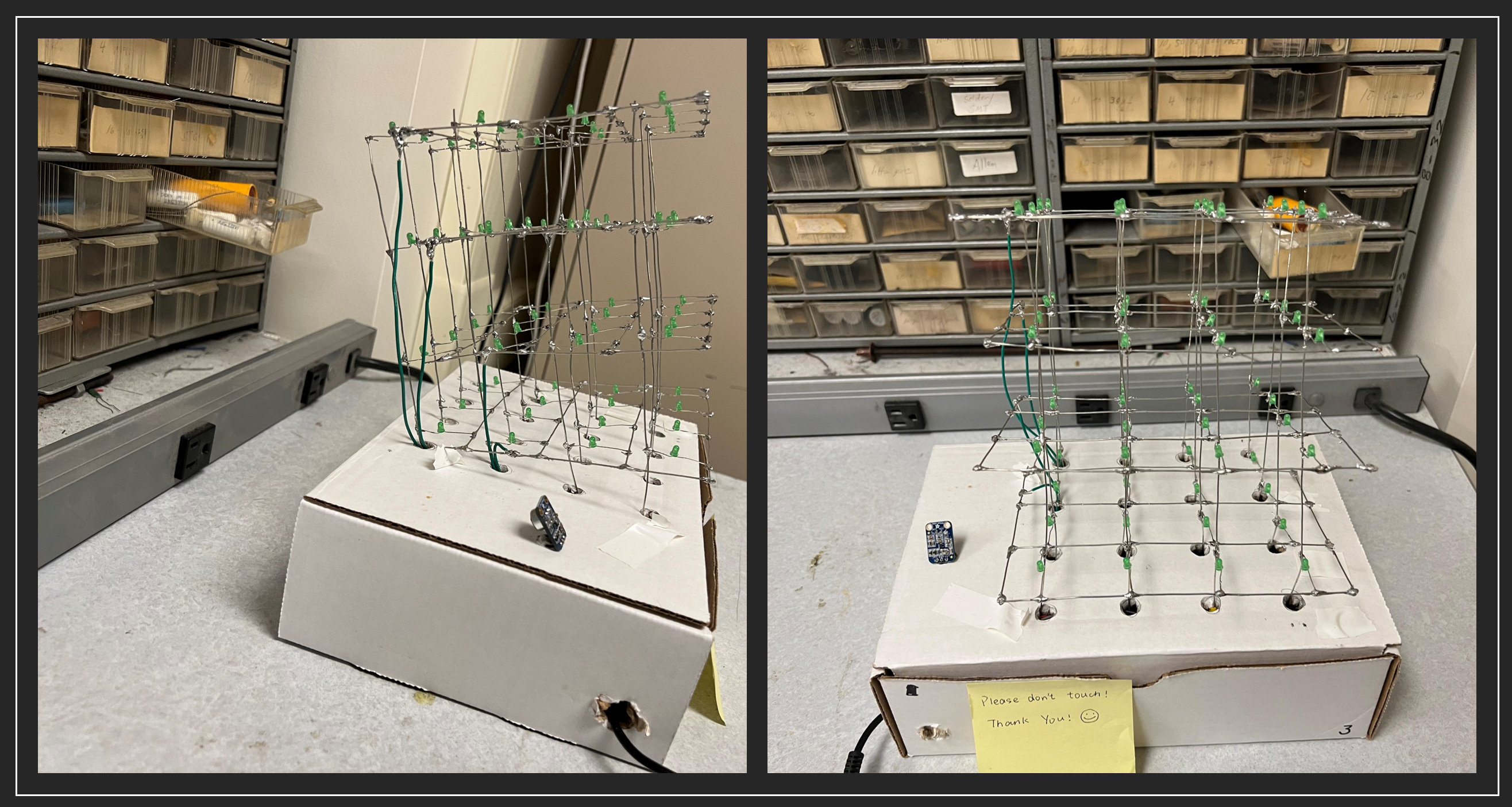
[Fall 2022] We build a 444 LED cube namedthe Leaning Cube of Pisathat can dance with the beating of the music!
- Suitable forB.Tech/B.E Embedded Systems students
- Build time4-6 weeks
- LevelBeginner
- Available atAjvika Labs, Kakinada
About this project
Toggle navigation
Dancing Cube
Introduction
High-Level Design
Software&Hardware
Results
Conclusions
Appendix A
Code Apendix
Dancing Cube
The Leaning Cube of Pisa
1.Introduction
We build a 4
4 LED cube named
the Leaning Cube of Pisa
that can dance with the beating of the music!
Electronic music visualization has been used to enhance the music listening experience for deaf and hard-of-hearing people. We want to create a gadget that visualizes music and makes music available to everyone in the globe in order to better assist deaf or hearing-impaired persons. Anyway, it’s really cool to build an LED Cube and make it dance to the rhythm of the music.
2. High-Level Design
The materials needed to build an LED cube are very simple and easy to obtain. Just some LEDs and some wires then we can build a LED cube. To set up an LED cube using a Pico projector and a microphone, we need to connect the Raspberrypi Pico to a computer that is capable of running the necessary software to control the LED cube and generate music visualization. The microphone would also need to be connected to the computer or device in order to capture the audio input.
Once everything is set up, we would need to use software to analyze the audio data from the microphone in real time, using the Fast Fourier Transform (FFT) algorithm to extract the frequency components of the music. This data can then be used to control the LED cube, causing the individual LEDs to light up or blink in a pattern that corresponds to the music.
It may also be necessary to use additional hardware, such as specialized LED drivers, to control the LED cube and ensure that it can respond quickly and accurately to the music visualization data. Overall, creating a music visualization system using an LED cube and a Pico projector would require a combination of hardware and software, as well as some knowledge of audio processing and LED control techniques.
In order to control a 4x4x4 LED cube, we would need to use a shift register with at least 64 output pins (16 pins per layer, with 4 layers in the cube). We would also need to use software or additional hardware, such as microcontrollers, to generate the data signals that will control the LED cube. Additionally, we may need to use specialized LED drivers or other hardware to ensure that the LED cube can be controlled accurately and efficiently.
3. Program and Hardware Design
3.1 Hardware Design
3.1.1 Components
As shown in the following Figure 1, the supplies for our project consist of Pi Pico, a microphone module, ninety-six 3mm green LEDs, four shift registers, twenty 100 Ohm resistors, 3.3 Voltage power, and many jumper cables. All components are connected to assemble the circuit manually, especially the LED cube. Therefore, the following parts will illustrate the circuit design, mechanism, and LED cube assembling process.
Fig.1. Components List
3.1.2 Circuit Design
The circuit of the dancing LED cube is designed as shown in the Figure 2. There are four shift registers used to control the four columns of the LED cube. Rows of LED cubes are controlled by four GPIO pins (GPIO 22, GPIO 21, GPIO 2, and GPIO 3). Four shift registers are connected to the microcontroller by 6 GPIO pins. All shift registers are connected to the 3.3 voltage output pin and ground pin on Pi Pico. GPIO 10 is used to input the storage-register clock (RCLK) signal to four shift registers. GPIO 11 is used to input the shift-register clock (SRCLK) to four shift registers. GPIO 9, GPIO 12, GPIO 13, and GPIO 14 are used to input serial signals to four shift registers respectively, and more controlling details will be indicated in the program design section.
For the microphone module, Vcc and GND pins are respectively connected to Pico’s 3.3 Voltage out pin and ground pin, and the output signal pin is connected to GPIO 26 to input the receiving signal to the microcontroller. After computing the corresponding frequency of receive voice, the LEDs will blink in a specific pattern (different layers, columns, and rows) for different frequencies, this mechanism will be explained in the software design part.
Fig.2. Mechanism of the circuit.
This figure includes possible important circuits of components. (Not all the GPIO and other exports have been shown in this figure, just conceptualized circuit figure).
As shown in Figure 3(a), the negative pins of one-layer LEDs are all connected, then one jumper wire is used to connect this layer’s negative wire to the GPIO pin (four layers of negative electrodes are connected to GPIO 22, GPIO 21, GPIO 2 and GPIO 3 respectively), which means the rows of LED cube can be controlled by four GPIO pins. Figure 3(b) shows the real layers built into the project.
Figure.3(a). Four-layer connection circuit of LEDs. 3(b). Real four-layer LED cube in process.
As shown in Figure 4(a) and (b), after four layers of LEDs are made successfully, positive electrodes of each column from layer one to layer four will be connected separately. Combined with the circuit shown in Figure 4, column LEDs can be controlled by shift registers respectively. By inputting different CLK signals from the microcontroller from GPIO pins, LEDs in different columns can blink in different patterns. More details in blink patterns will be explained in the software design part.
Figure.4(a). Four-layer connection circuit of LEDs. 4(b). Real four-layer LED cube in process.
3.2 Software Design
3.2.1 Shift Register
The 74HC595 is a popular shift register integrated circuit (IC) that is commonly used to expand the output pins on a microcontroller. It allows a microcontroller to control a large number of outputs by using only a few digital pins. This makes it ideal for applications where there are many LEDs or other output devices that need to be controlled independently. It can be used in a wide range of projects, from simple LED displays to complex robotics projects.
As shown in Figure 5, we initialize all 4 shift registers to create a col_1_reg, col_2_reg, col_3_reg, and col_4_reg.
Figure.5. Shift register init code
We connect each layer directly to the Pico’s pin and set the pin as the output model as shown in Figure 6.
Figure.6. 4 Layers init code
Then we define 8 different models for music virtualization. The image below shows how the different models are illuminated, with eight different modes corresponding to a-h.
Figure.7. 8 different models
As shown in Figure 8, the first value col_val = 0b11110000 represents the input serial value of the shift register. We input 0b11110000 to set the shift register output QB, QC, QD, QE, and QF to high voltage. And then we flush the value to the first register col_1_reg. On other hand, deciding which layer is lit is done by pulling that layer to digital low. For instance, we use gpio_put(ROW_4, 0) to make sure only the bottom layer will be connected to the ground. The effect of this function is exactly what is shown in Figure 7(a).
Figure.8. draw model code
3.2.2 FFT Algorithm
As mentioned earlier in lab 1, the FFT (Fast Fourier Transform) is an algorithm that can be used to compute the discrete Fourier transform of a sequence of complex numbers. This means that if we have a sound signal that we want to analyze in the frequency domain, we can first convert it into a sequence of complex numbers and then apply the FFT algorithm to compute the DFT. This will give us a transformed sequence of complex numbers that represents the frequencies present in the original sound signal.
To use the FFT for analyzing a sound signal, we will need to first digitize the signal by sampling it at regular intervals and quantizing the samples to represent them as a sequence of numbers. This will give us a sequence of complex numbers that you can input into the FFT algorithm. Then, we can apply the FFT to compute the DFT of the sequence and obtain the transformed sequence of complex numbers. This transformed sequence will contain information about the frequencies present in the original sound signal, which we can then analyze to learn more about the characteristics of the signal.
As shown in Figure 9, after we get the max_freqency, we divide the sound frequencies into 8 ranges, from 0 to 2000, with different ranges corresponding to different drawFFTLayer() functions. The achieved effect is the a-h in Figure XXX
Figure.9. Frequency reaction code
3.3 Some Difficulties
The first difficulty in hardware design is how to connect the LEDs layer by layer. It’s very difficult to connect them vertically and trimly without any tools. Thanks to the grid board provided by Prof. Hunter (Figure 10), the initial grid could be built smoothly. Another difficulty in this part is how to make sure each layer’s LEDs are correctly aligned. This requires us to check each LED in the right position (right connection for both negative and positive anodes) row by row and layer by layer. If one of the LEDs is connected in the wrong direction, the LED cube cannot work correctly. Besides, the biggest difficulty in this part is how to solder each LED firmly, this requires high patience and great welding skills.
Figure.10. Grid board for welding LED layers.
Another tricky point is about the software that uses shift registers. We need to input the bit number like 0b1111000 and we need to set up a connection between the real LED cube and the bit number. We also have 4 different registers and 4 layers. We abstract the bit number and the different shift registers and different layers to a function called drawOnePoint(x,y,z). Through this function, we only need to input the 3D coordinates of the LED cube and it could help us to light up the corresponding LED.
4. Results
4.1 Demo Video
Demonstration Video
Therefore, this project has great usability for us or other people. Based on the circuit and codes shown in the report, it is feasible to build larger dancing LED cubes and even more dancing and flowing pattern of LEDs.
4.2 Testing
We need to t
Dancing Cube
Introduction
High-Level Design
Software&Hardware
Results
Conclusions
Appendix A
Code Apendix
Dancing Cube
The Leaning Cube of Pisa
1.Introduction
We build a 4
4 LED cube named
the Leaning Cube of Pisa
that can dance with the beating of the music!
Electronic music visualization has been used to enhance the music listening experience for deaf and hard-of-hearing people. We want to create a gadget that visualizes music and makes music available to everyone in the globe in order to better assist deaf or hearing-impaired persons. Anyway, it’s really cool to build an LED Cube and make it dance to the rhythm of the music.
2. High-Level Design
The materials needed to build an LED cube are very simple and easy to obtain. Just some LEDs and some wires then we can build a LED cube. To set up an LED cube using a Pico projector and a microphone, we need to connect the Raspberrypi Pico to a computer that is capable of running the necessary software to control the LED cube and generate music visualization. The microphone would also need to be connected to the computer or device in order to capture the audio input.
Once everything is set up, we would need to use software to analyze the audio data from the microphone in real time, using the Fast Fourier Transform (FFT) algorithm to extract the frequency components of the music. This data can then be used to control the LED cube, causing the individual LEDs to light up or blink in a pattern that corresponds to the music.
It may also be necessary to use additional hardware, such as specialized LED drivers, to control the LED cube and ensure that it can respond quickly and accurately to the music visualization data. Overall, creating a music visualization system using an LED cube and a Pico projector would require a combination of hardware and software, as well as some knowledge of audio processing and LED control techniques.
In order to control a 4x4x4 LED cube, we would need to use a shift register with at least 64 output pins (16 pins per layer, with 4 layers in the cube). We would also need to use software or additional hardware, such as microcontrollers, to generate the data signals that will control the LED cube. Additionally, we may need to use specialized LED drivers or other hardware to ensure that the LED cube can be controlled accurately and efficiently.
3. Program and Hardware Design
3.1 Hardware Design
3.1.1 Components
As shown in the following Figure 1, the supplies for our project consist of Pi Pico, a microphone module, ninety-six 3mm green LEDs, four shift registers, twenty 100 Ohm resistors, 3.3 Voltage power, and many jumper cables. All components are connected to assemble the circuit manually, especially the LED cube. Therefore, the following parts will illustrate the circuit design, mechanism, and LED cube assembling process.
Fig.1. Components List
3.1.2 Circuit Design
The circuit of the dancing LED cube is designed as shown in the Figure 2. There are four shift registers used to control the four columns of the LED cube. Rows of LED cubes are controlled by four GPIO pins (GPIO 22, GPIO 21, GPIO 2, and GPIO 3). Four shift registers are connected to the microcontroller by 6 GPIO pins. All shift registers are connected to the 3.3 voltage output pin and ground pin on Pi Pico. GPIO 10 is used to input the storage-register clock (RCLK) signal to four shift registers. GPIO 11 is used to input the shift-register clock (SRCLK) to four shift registers. GPIO 9, GPIO 12, GPIO 13, and GPIO 14 are used to input serial signals to four shift registers respectively, and more controlling details will be indicated in the program design section.
For the microphone module, Vcc and GND pins are respectively connected to Pico’s 3.3 Voltage out pin and ground pin, and the output signal pin is connected to GPIO 26 to input the receiving signal to the microcontroller. After computing the corresponding frequency of receive voice, the LEDs will blink in a specific pattern (different layers, columns, and rows) for different frequencies, this mechanism will be explained in the software design part.
Fig.2. Mechanism of the circuit.
This figure includes possible important circuits of components. (Not all the GPIO and other exports have been shown in this figure, just conceptualized circuit figure).
As shown in Figure 3(a), the negative pins of one-layer LEDs are all connected, then one jumper wire is used to connect this layer’s negative wire to the GPIO pin (four layers of negative electrodes are connected to GPIO 22, GPIO 21, GPIO 2 and GPIO 3 respectively), which means the rows of LED cube can be controlled by four GPIO pins. Figure 3(b) shows the real layers built into the project.
Figure.3(a). Four-layer connection circuit of LEDs. 3(b). Real four-layer LED cube in process.
As shown in Figure 4(a) and (b), after four layers of LEDs are made successfully, positive electrodes of each column from layer one to layer four will be connected separately. Combined with the circuit shown in Figure 4, column LEDs can be controlled by shift registers respectively. By inputting different CLK signals from the microcontroller from GPIO pins, LEDs in different columns can blink in different patterns. More details in blink patterns will be explained in the software design part.
Figure.4(a). Four-layer connection circuit of LEDs. 4(b). Real four-layer LED cube in process.
3.2 Software Design
3.2.1 Shift Register
The 74HC595 is a popular shift register integrated circuit (IC) that is commonly used to expand the output pins on a microcontroller. It allows a microcontroller to control a large number of outputs by using only a few digital pins. This makes it ideal for applications where there are many LEDs or other output devices that need to be controlled independently. It can be used in a wide range of projects, from simple LED displays to complex robotics projects.
As shown in Figure 5, we initialize all 4 shift registers to create a col_1_reg, col_2_reg, col_3_reg, and col_4_reg.
Figure.5. Shift register init code
We connect each layer directly to the Pico’s pin and set the pin as the output model as shown in Figure 6.
Figure.6. 4 Layers init code
Then we define 8 different models for music virtualization. The image below shows how the different models are illuminated, with eight different modes corresponding to a-h.
Figure.7. 8 different models
As shown in Figure 8, the first value col_val = 0b11110000 represents the input serial value of the shift register. We input 0b11110000 to set the shift register output QB, QC, QD, QE, and QF to high voltage. And then we flush the value to the first register col_1_reg. On other hand, deciding which layer is lit is done by pulling that layer to digital low. For instance, we use gpio_put(ROW_4, 0) to make sure only the bottom layer will be connected to the ground. The effect of this function is exactly what is shown in Figure 7(a).
Figure.8. draw model code
3.2.2 FFT Algorithm
As mentioned earlier in lab 1, the FFT (Fast Fourier Transform) is an algorithm that can be used to compute the discrete Fourier transform of a sequence of complex numbers. This means that if we have a sound signal that we want to analyze in the frequency domain, we can first convert it into a sequence of complex numbers and then apply the FFT algorithm to compute the DFT. This will give us a transformed sequence of complex numbers that represents the frequencies present in the original sound signal.
To use the FFT for analyzing a sound signal, we will need to first digitize the signal by sampling it at regular intervals and quantizing the samples to represent them as a sequence of numbers. This will give us a sequence of complex numbers that you can input into the FFT algorithm. Then, we can apply the FFT to compute the DFT of the sequence and obtain the transformed sequence of complex numbers. This transformed sequence will contain information about the frequencies present in the original sound signal, which we can then analyze to learn more about the characteristics of the signal.
As shown in Figure 9, after we get the max_freqency, we divide the sound frequencies into 8 ranges, from 0 to 2000, with different ranges corresponding to different drawFFTLayer() functions. The achieved effect is the a-h in Figure XXX
Figure.9. Frequency reaction code
3.3 Some Difficulties
The first difficulty in hardware design is how to connect the LEDs layer by layer. It’s very difficult to connect them vertically and trimly without any tools. Thanks to the grid board provided by Prof. Hunter (Figure 10), the initial grid could be built smoothly. Another difficulty in this part is how to make sure each layer’s LEDs are correctly aligned. This requires us to check each LED in the right position (right connection for both negative and positive anodes) row by row and layer by layer. If one of the LEDs is connected in the wrong direction, the LED cube cannot work correctly. Besides, the biggest difficulty in this part is how to solder each LED firmly, this requires high patience and great welding skills.
Figure.10. Grid board for welding LED layers.
Another tricky point is about the software that uses shift registers. We need to input the bit number like 0b1111000 and we need to set up a connection between the real LED cube and the bit number. We also have 4 different registers and 4 layers. We abstract the bit number and the different shift registers and different layers to a function called drawOnePoint(x,y,z). Through this function, we only need to input the 3D coordinates of the LED cube and it could help us to light up the corresponding LED.
4. Results
4.1 Demo Video
Demonstration Video
Therefore, this project has great usability for us or other people. Based on the circuit and codes shown in the report, it is feasible to build larger dancing LED cubes and even more dancing and flowing pattern of LEDs.
4.2 Testing
We need to t
Technologies used
Hardware components
- microphone
Software & tools
- C
- Arduino IDE
What you get
- Working project / hardware kit, tested before delivery
- Complete source code with explanation
- Project demo and guidance for your viva
- Project report, PPT and IEEE paper support (on request)
Delivery & Payment
Delivery takes a minimum of two weeks from the date your inquiry is confirmed.
Payment is in two parts:
• 50% advance to start the project
• Remaining 50% before delivery
Note:
• Documentation and PPT are not included by default
• If you need documentation/PPT, it can be arranged for extra time and cost
We'll confirm the exact timeline and cost with you after reviewing your requirements.
Related Embedded Systems projects

Embedded Systems
Gas Leakage Detector Using Arduino
A budget-friendly LPG gas leak detector built with an Arduino and MQ-5 gas sensor, triggering a buzzer and LED when unsafe gas levels are de...
View project
Embedded Systems
Simple Alarm System
A beginner-friendly home alarm with PIR motion sensing, keypad PIN entry, and separate entry/exit timing delays, built to be easy to expand.
View project
Embedded Systems
Ultrasonic Sensor Project with Arduino UNO Q
A beginner-friendly first Arduino UNO Q project: a servo-swept ultrasonic sensor that renders a live sweeping radar display in a web browser...
View project
Embedded Systems
3D Audio Localization
[Fall 2025] We designed a real-time embedded system that localizes sound sources in three dimensions and visualizes them live using a four-m...
View project