Crowd City on Pico
[Fall 2022] This project implements a two-player video game through the combination of hardware and software based on RP2040 microcontroller.
- Suitable forB.Tech/B.E Embedded Systems students
- Build time4-6 weeks
- LevelBeginner
- Available atAjvika Labs, Kakinada
About this project

Table of contents

Introduction
High-level Design
Program/Hardware Design
Results
Conclusion
Appendix
In [ ]:
from
IPython.display
import
YouTubeVideo
YouTubeVideo
(
"https://www.youtube.com/watch?v=m4_iMseZTsA&list=PLDqMkB5cbBA6AwYC_DElkDStUdOsTuIL7&index=38"
width
=
height
=
)
Out[ ]:
Introduction

This project implements a two-player video game through the combination of hardware and software based on RP2040 microcontroller.
From the developer’s perspective, this project is an embedded video game project designed for entertainment. In lab 2 of course 5730, the team learned the concept of boids and their behavior. During the process of coming up with ideas for the final project, the team found an interesting online game called Crowd City. Inspired by these two, the team decided to create a user-controllable video game based on what we learned in this course.
From the user’s perspective, the players could control and play the game using the two joysticks. The user interface is shown on the VGA screen. After choosing the game time on the initial interface, the players could start playing the game. During the game, each player could control a leading boid on the screen to move and infect other free boids. Those infected free boids would become members of the player’s group and the player with a larger amount of members at the end is the winner. The player should move its leading boid smartly to enlarge its group as fast as possible. Whenever the group size of one player increases and exceeds the amount of another group, a warning sound would be generated. If the time for the current game is less than five seconds, a timing sound would keep alarming until the game ends. Finally, the game ends and the winner would be shown on the screen.
High-level design

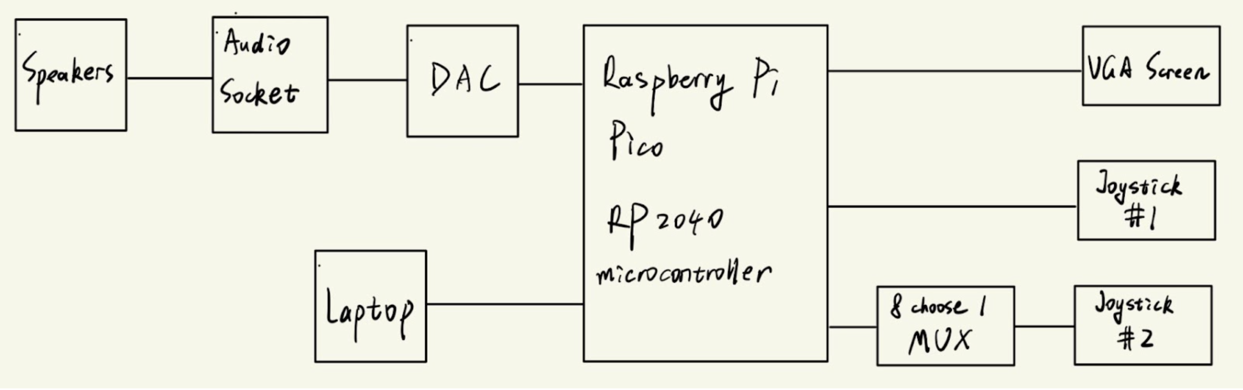
The high-level design for the hardware part is shown as the diagram in the following figure. As one can see, the core of this project is Raspberry Pi Pico development board with RP2040 microcontroller. Other hardwares are outfitted on the breadboard with physical wire. On the top-left corner, the diagram shows the part about generating sound. The team first connects Pico to the DAC converter and then connect the DAC converter to the audio socket. By this way, the digital signal generated by the Pico could be converted into analog signal and further human-detectable sound. Finally, the signal is played by the speakers connected to the audio socket. On the top-right corner, the diagram shows the part about display. In order to display the user interface of this game, the team simply needs to connect the Pico to a VGA screen. On the bottom-left corner, the diagram shows how the Pico is programmed. In this project, the team makes use of Mac laptop to write the code and program into the Pico. On the bottom-right corner, the diagram shows how the users could interact with this system. As one can see, the team first connects one joystick to the Pico directly and then insert a MUX between the Pico and the second joystick. This is because one joystick needs to use two ADC channels. Since the Pico only has three usable ADC channels, the second joystick can’t be connected to the Pico directly. Instead, the team makes use of a Mux to switch the two inputs from the second joystick and output one signal to the Pico. Since the switching delay is so small such that the user couldn’t tell the difference, this design is acceptable.
For the software part, the team defines the concepts and some initial rules for the game as the following.
Basic concepts:
Boid: moving unit on the screen, use the same concept as in lab 2 of the course.
Leading boid: the boid that could be controlled by the user via joystick, bigger than other boids and has its own color.
Free boid: the boid that moves freely and randomly with white color.
Group: some organized boids moving together led by the leading boid and they have the same color as the leading boid.
Infection: a boid is absorbed into one group compulsively.
Infection rules:
When the leading boid is close to other free boids, the free boids are infected by the leading boid, and their colors will be changed to the same as the leading boid. In the code, this is implemented by the free boid side. That is, when a free boid sees a leading boid in its infected range, it changes its color. In the case it sees two leading boids, it chooses the one with a smaller distance.
The infected range is the same as the protected range of the Separation algorithm in lab 2 of the course. After that, they will follow the leading boid.
The leading boids couldn’t be infected! So the team only focuses on the update of the free boids.
Following rules:
Non-leading boids in the group will follow the leading boid of that group through some organic mechanism (like what we did in lab 2). For example, there will be some matching, alignment, and separation effects. We will introduce some new rules for boids in the group to align and catch up with the leading boid.
Battle rules:
When two (or more) different groups meet together, the boids in the group with a smaller amount will be infected by another one. But it can flee as fast as possible. Notice that the member instead of the leading boid in a specific group could also affect members in other groups.
Unfollowing rules:
An infected boid has a low probability to unfollow the current leading boid (configured by own bias). Also, it is possible for boids at the margins of the group to unfollow the leading boid. For example, if the leading boid is not in the visual range of the boid, boid will unfollow the leading boid, but might still have the tendency to follow the group.
Other rules:
Use of colors to indicate boids: we will use white pixels to indicate free boids, green to indicate one crowd, and red to indicate the other crowd. We will also add some additional notations to indicate which two boids are leading boids.
Timing: Each game has time limit. It could also be user input.
Program/hardware design

The hardware used for this project is listed as below.
Raspberry Pi Pico with dual-core RP2040 (# 7 in figure )
DAC converter (# 3 in figure )
3.5mm audio socket (# 2 in figure)
Two speakers
VGA Screen (connected cable is # 1 in figure )
Mac Laptop
8 choose 1 MUX, Model CD4051BE (# 5 in figure )
Two joysticks (# 4 in figure )
UART
Button (# 6 in figure )
The hardware setup and connection is shown in figures below. Note that the VDD of Joystick 2 is also connected to the Pico 3.3V output.
In addition, since this is the first time the team tries to make use of a MUX, the team meets a lot of issues when debugging the hardware part related to the MUX. The most important one is that the team forgets to connect the VEE and INH PIN of the MUX to the ground at first. As a result, the team observes a strange bug in the system. Specifically speaking, when using one channel input from the joystick, the output signal to the Pico is correct. But once we connect two channel inputs from the joystick and switch between them, the output signal would become some unexpected results. This is really hard to debug since the MUX does work when there’s only one channel input and the software part has nothing to do with it. The team finally figured out the bug by checking the circuit example in the MUX datasheet carefully.
Hardware setup
Connections
Sound effect algorithm

In order to increase the user experience, the team adds some sound effects to the system. The sound generation algorithm is based on the direct digital synthesis of lab 1 of this course.
There are three possible sound effects generated during the game. When the size of one group exceeds the size of another group by a certain amount, the Pico would generate a beep sound. Two different frequencies are designed for the two cases: the red group size is larger than the green group size or the green group size is larger than the red group size. In addition, when the remained time for the current game is less than 5 seconds, a continuous alarm sound would be generated to warn the players.
The technical details come from the algorithm and logic of lab 1. The major difference is that in this project, the team only uses core 1 to generate the sound. This is because core 0 is dedicated to controlling the boids in order to maximize performance and the number of boids. Since only core 1 is used for sound generation, the system could only generate one kind of sound at a specific moment. The sound selection is controlled by the global variables in the code.
Joystick control algorithm

This project requires the players to use joysticks to interact with the system. There are only two joysticks connected to the system and each player uses one of them to control the leading boid. One of the joysticks is the master joystick and only this joystick could be used to control the game mode selection and game reset.
When using the joystick to play, the player needs to hold the joystick in the correct direction such that the text on the joystick could be read normally. In this way, when the player moves the joystick to the left, the leading boid would move to the left on the screen. During the initial user interface on the screen, the player could use the master joystick to choose the time of the game. Once the time is confirmed, the player could press the master joystick in the middle and the game would start. After the game is over, the player could press the master joystick in the middle again to reset the game.
Before we dive into the algorithm, one should know what kind of data the joystick generates and send to the Pico. The joystick has two outputs: VRx and VRy, which correspond to the current position of the top of the joystick. The joystick uses 12 bits to encode the x and y values, which means the range of the value for x and y is [0, 4095]. When the joystick is in the normal position (not moved by the player), the output v
Table of contents

Introduction
High-level Design
Program/Hardware Design
Results
Conclusion
Appendix
In [ ]:
from
IPython.display
import
YouTubeVideo
YouTubeVideo
(
"https://www.youtube.com/watch?v=m4_iMseZTsA&list=PLDqMkB5cbBA6AwYC_DElkDStUdOsTuIL7&index=38"
width
=
height
=
)
Out[ ]:
Introduction

This project implements a two-player video game through the combination of hardware and software based on RP2040 microcontroller.
From the developer’s perspective, this project is an embedded video game project designed for entertainment. In lab 2 of course 5730, the team learned the concept of boids and their behavior. During the process of coming up with ideas for the final project, the team found an interesting online game called Crowd City. Inspired by these two, the team decided to create a user-controllable video game based on what we learned in this course.
From the user’s perspective, the players could control and play the game using the two joysticks. The user interface is shown on the VGA screen. After choosing the game time on the initial interface, the players could start playing the game. During the game, each player could control a leading boid on the screen to move and infect other free boids. Those infected free boids would become members of the player’s group and the player with a larger amount of members at the end is the winner. The player should move its leading boid smartly to enlarge its group as fast as possible. Whenever the group size of one player increases and exceeds the amount of another group, a warning sound would be generated. If the time for the current game is less than five seconds, a timing sound would keep alarming until the game ends. Finally, the game ends and the winner would be shown on the screen.
High-level design

The high-level design for the hardware part is shown as the diagram in the following figure. As one can see, the core of this project is Raspberry Pi Pico development board with RP2040 microcontroller. Other hardwares are outfitted on the breadboard with physical wire. On the top-left corner, the diagram shows the part about generating sound. The team first connects Pico to the DAC converter and then connect the DAC converter to the audio socket. By this way, the digital signal generated by the Pico could be converted into analog signal and further human-detectable sound. Finally, the signal is played by the speakers connected to the audio socket. On the top-right corner, the diagram shows the part about display. In order to display the user interface of this game, the team simply needs to connect the Pico to a VGA screen. On the bottom-left corner, the diagram shows how the Pico is programmed. In this project, the team makes use of Mac laptop to write the code and program into the Pico. On the bottom-right corner, the diagram shows how the users could interact with this system. As one can see, the team first connects one joystick to the Pico directly and then insert a MUX between the Pico and the second joystick. This is because one joystick needs to use two ADC channels. Since the Pico only has three usable ADC channels, the second joystick can’t be connected to the Pico directly. Instead, the team makes use of a Mux to switch the two inputs from the second joystick and output one signal to the Pico. Since the switching delay is so small such that the user couldn’t tell the difference, this design is acceptable.
For the software part, the team defines the concepts and some initial rules for the game as the following.
Basic concepts:
Boid: moving unit on the screen, use the same concept as in lab 2 of the course.
Leading boid: the boid that could be controlled by the user via joystick, bigger than other boids and has its own color.
Free boid: the boid that moves freely and randomly with white color.
Group: some organized boids moving together led by the leading boid and they have the same color as the leading boid.
Infection: a boid is absorbed into one group compulsively.
Infection rules:
When the leading boid is close to other free boids, the free boids are infected by the leading boid, and their colors will be changed to the same as the leading boid. In the code, this is implemented by the free boid side. That is, when a free boid sees a leading boid in its infected range, it changes its color. In the case it sees two leading boids, it chooses the one with a smaller distance.
The infected range is the same as the protected range of the Separation algorithm in lab 2 of the course. After that, they will follow the leading boid.
The leading boids couldn’t be infected! So the team only focuses on the update of the free boids.
Following rules:
Non-leading boids in the group will follow the leading boid of that group through some organic mechanism (like what we did in lab 2). For example, there will be some matching, alignment, and separation effects. We will introduce some new rules for boids in the group to align and catch up with the leading boid.
Battle rules:
When two (or more) different groups meet together, the boids in the group with a smaller amount will be infected by another one. But it can flee as fast as possible. Notice that the member instead of the leading boid in a specific group could also affect members in other groups.
Unfollowing rules:
An infected boid has a low probability to unfollow the current leading boid (configured by own bias). Also, it is possible for boids at the margins of the group to unfollow the leading boid. For example, if the leading boid is not in the visual range of the boid, boid will unfollow the leading boid, but might still have the tendency to follow the group.
Other rules:
Use of colors to indicate boids: we will use white pixels to indicate free boids, green to indicate one crowd, and red to indicate the other crowd. We will also add some additional notations to indicate which two boids are leading boids.
Timing: Each game has time limit. It could also be user input.
Program/hardware design

The hardware used for this project is listed as below.
Raspberry Pi Pico with dual-core RP2040 (# 7 in figure )
DAC converter (# 3 in figure )
3.5mm audio socket (# 2 in figure)
Two speakers
VGA Screen (connected cable is # 1 in figure )
Mac Laptop
8 choose 1 MUX, Model CD4051BE (# 5 in figure )
Two joysticks (# 4 in figure )
UART
Button (# 6 in figure )
The hardware setup and connection is shown in figures below. Note that the VDD of Joystick 2 is also connected to the Pico 3.3V output.
In addition, since this is the first time the team tries to make use of a MUX, the team meets a lot of issues when debugging the hardware part related to the MUX. The most important one is that the team forgets to connect the VEE and INH PIN of the MUX to the ground at first. As a result, the team observes a strange bug in the system. Specifically speaking, when using one channel input from the joystick, the output signal to the Pico is correct. But once we connect two channel inputs from the joystick and switch between them, the output signal would become some unexpected results. This is really hard to debug since the MUX does work when there’s only one channel input and the software part has nothing to do with it. The team finally figured out the bug by checking the circuit example in the MUX datasheet carefully.
Hardware setup
Connections
Sound effect algorithm

In order to increase the user experience, the team adds some sound effects to the system. The sound generation algorithm is based on the direct digital synthesis of lab 1 of this course.
There are three possible sound effects generated during the game. When the size of one group exceeds the size of another group by a certain amount, the Pico would generate a beep sound. Two different frequencies are designed for the two cases: the red group size is larger than the green group size or the green group size is larger than the red group size. In addition, when the remained time for the current game is less than 5 seconds, a continuous alarm sound would be generated to warn the players.
The technical details come from the algorithm and logic of lab 1. The major difference is that in this project, the team only uses core 1 to generate the sound. This is because core 0 is dedicated to controlling the boids in order to maximize performance and the number of boids. Since only core 1 is used for sound generation, the system could only generate one kind of sound at a specific moment. The sound selection is controlled by the global variables in the code.
Joystick control algorithm

This project requires the players to use joysticks to interact with the system. There are only two joysticks connected to the system and each player uses one of them to control the leading boid. One of the joysticks is the master joystick and only this joystick could be used to control the game mode selection and game reset.
When using the joystick to play, the player needs to hold the joystick in the correct direction such that the text on the joystick could be read normally. In this way, when the player moves the joystick to the left, the leading boid would move to the left on the screen. During the initial user interface on the screen, the player could use the master joystick to choose the time of the game. Once the time is confirmed, the player could press the master joystick in the middle and the game would start. After the game is over, the player could press the master joystick in the middle again to reset the game.
Before we dive into the algorithm, one should know what kind of data the joystick generates and send to the Pico. The joystick has two outputs: VRx and VRy, which correspond to the current position of the top of the joystick. The joystick uses 12 bits to encode the x and y values, which means the range of the value for x and y is [0, 4095]. When the joystick is in the normal position (not moved by the player), the output v
Technologies used
Hardware components
- RP2040
- Raspberry Pi Pico
- speaker
- DAC
- ADC
Software & tools
- Python
Project demo video
What you get
- Working project / hardware kit, tested before delivery
- Complete source code with explanation
- Project demo and guidance for your viva
- Project report, PPT and IEEE paper support (on request)
Delivery & Payment
Delivery takes a minimum of two weeks from the date your inquiry is confirmed.
Payment is in two parts:
• 50% advance to start the project
• Remaining 50% before delivery
Note:
• Documentation and PPT are not included by default
• If you need documentation/PPT, it can be arranged for extra time and cost
We'll confirm the exact timeline and cost with you after reviewing your requirements.
Related Embedded Systems projects

Embedded Systems
Gas Leakage Detector Using Arduino
A budget-friendly LPG gas leak detector built with an Arduino and MQ-5 gas sensor, triggering a buzzer and LED when unsafe gas levels are de...
View project
Embedded Systems
Simple Alarm System
A beginner-friendly home alarm with PIR motion sensing, keypad PIN entry, and separate entry/exit timing delays, built to be easy to expand.
View project
Embedded Systems
Ultrasonic Sensor Project with Arduino UNO Q
A beginner-friendly first Arduino UNO Q project: a servo-swept ultrasonic sensor that renders a live sweeping radar display in a web browser...
View project
Embedded Systems
3D Audio Localization
[Fall 2025] We designed a real-time embedded system that localizes sound sources in three dimensions and visualizes them live using a four-m...
View project