Computron The parallel computer of the future
This webpage is the final report for our final project in ECE 4760 Microcontrollers Fall 2023.
- Suitable forB.Tech/B.E Embedded Systems students
- Build time4-6 weeks
- LevelBeginner
- Available atAjvika Labs, Kakinada
About this project
Introduction
High-Level Design
Program/Hardware Design
Results
Conclusion
Appendix
Computron: The Parallel Computer of the Future
This webpage is the final report for our final project in ECE 4760 Microcontrollers Fall 2023.
Project Introduction
For our final project, we built Computron, a parallel computer consisting of Raspberry Pi Picos that communicate over a I2C bus. To demonstrate the power
of parallel computation among these devices, the Mandelbrot set is computed across Picos. Every Pico computes a portion of the set, while one is also
responsible for projecting the set onto a VGA monitor. This projection unit is special, in that it is the only peripheral device on the I2C bus while every
other Pico is an I2C controller. We were able to configure the projection unit to dynamically recognize the number of controllers on the network prior to
computation, and to distribute work accordingly without a user informing the network directly. In the end, with eight Picos connected together we were able
to achieve about a four-times speedup in computation of the Mandelbrot set compared to computation on a single Pico.
High-Level Design
After completing Lab 2, both of us were still captivated by optimizing the Boids program even further than we were able to initially. Besides implementing
more direct software optimizations to put more Boids onto the screen, the idea of running the program across multiple Picos came up. We reasoned that the
boost to computation power would offset the incurred communication overhead enough to create a nonnegligible speedup. However, parallelizing the Boids
program in particular appeared daunting, due to the problem of sharing all the necessary boid information across Picos in a timely fashion. Moreover, the
time constraint of the project itself posed to be a concern. Thus, in large part due to advice from Professor Land, we decided to instead parallelize the
Mandelbrot set program from the ECE 4760's demonstration code.
Originally, we did not plan on using I2C as our final communication protocol. Instead, we had planned on using CAN as our network protocol. To us, CAN was
a sound compromise between the speed of SPI and the ease of use of I2C. However, because our CAN transceivers came in later than expected, we decided to
start our work with I2C. Though we wished to be able to implement our project in both I2C and CAN in order to compare the two, we ended up only having time
to implement the I2C version of our parallel computer.
Besides its inherent aesthetic appeal, the Mandelbrot set also serves as an excellent benchmark for parallel computation power, in that its algorithm contains
no dependencies between results. This means that work can be done simultaneously on many different devices, and none of them ever rely on the results of
another device. To put this into computer architecture language, the algorithm presents no possible data hazards.
From the outset, there was an obvious networking overhead tradeoff that would be incurred as Picos were added to the network. While each additional Pico would
afford the network two more cores to use for Mandelbrot computation, it also would further crowd the single I2C bus connecting every device on the network. This
meant that doubling the number of Picos would not necessarily halve the computation time for the entire Mandelbrot set, and that at some point we would essentially
reach a horizontal asymptote as far as performance went. The severity of this overhead would have likely been diminished if we had decided on a different type of
network as well. For instance, a tree-like network of Picos using SPI would probably not see diminishing returns as quickly, because not all devices would share
a bus and SPI itself has a greater transfer rate than I2C. However, because of time constraints, we decided that a simpler, single bus I2C network would still
function well enough.
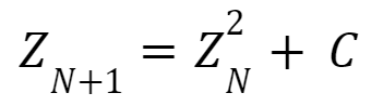
Beyond its immediate aesthetic appeal, the Mandelbrot set is interesting primarily because it is the result of relatively simple math. The following equation is the
core of the Mandelbrot set, and is applied to points on the coordinate plane:
In this equation, Z is a complex number that is equal to zero before its first iteration. C is a constant, complex number that is taken to be the x and y coordinates
at that point on the plane (where x is the real component and y is the imaginary component). Though this equation on its own may seem insignificant, what makes it
significant is how it is interpreted. Specifically, if Z diverges at a given coordinate, then this point is said to not be contained in the Mandelbrot set. Accordingly,
if Z does not diverge and is in fact stable, then the point is contained by the set. Essentially, Mandelbrot at its core is a plot showing which coordinates produce a
stable result for the above equation.
To make this underlying math work efficiently on the Pico, some simplifications and tricks are used. First of all, and perhaps most importantly, testing divergences to
infinity is not feasible without limiting the number of iterations done for the Mandelbrot equation to a reasonable number. In the case of our implementation, the Mandelbrot
math will only go up to a thousand iterations. Moreover, there must be a threshold magnitude beyond which Z is guaranteed to diverge and thus not belong to the set. In our
implementation, this threshold is set to equal two. It is difficult to explain why the number allows for the computation to function correctly, but an intuitive observation
to make that may help one understand is that two is the largest number you can subtract from its own square and have a difference less than or equal to that number.
Another mathematical adjustment made to allow the Mandelbrot set to generate properly is the scaling of coordinates. For our implementation, a 640x480 pixel VGA monitor is used
for displaying the resulting set. However, for the set to generate cleanly within these bounds the raw pixel coordinates must be scaled. For following equations scale the x and
y coordinates so that they properly produce the Mandelbrot set for our purposes:
Lastly, the Mandelbrot set is much more interesting when it is not only shown which coordinates diverge and which do not but also how quickly points outside of the set diverge.
To demonstrate this, pixels can be colored depending on how many iterations it takes for their coordinates' complex magnitudes to exceed the threshold of two. In the follow table,
the way iteration counts determine a pixel's color is explained:
Beyond the math behind the Mandelbrot set itself, our setup logic was also very important, as this determined how work was distributed across Picos. It is because of the way that
setup is completed that all Picos except the projection unit are marked as I2C controllers, while the projection unit itself is set as an I2C peripheral. The communication between
devices is explained in the following steps:
1. A math unit (I2C controller) takes control of the I2C line shared between all units when it is available, and reads from the projection unit
2. The projection unit writes to this math unit with the total count of Picos on the network thus far. If this is the first math unit to contact the
projection unit, for instance, then the count will just be one. This value becomes the ID for that math unit.
3. Once a second has elapsed, it is assumed that the projection unit has the total count of Picos on the network. This unit then writes the total count to all of the math units.
4. The math unit is responsible for computing all columns of the Mandelbrot set whose x coordinates are divisible by the total number of Picos after being already subtracted by the
unit's Pico ID. For example, a math unit with an ID of 3 in a network of eight Picos is responsible for columns of x coordinates 3, 11, 19, and so on up until 640. The projection unit
is also responsible for computation, and assigns itself with an ID of 0.
5. As pixels are computed on the math unit, if the resulting color is not black then the information for that pixel is written to the central projection unit to be put onto the monitor.
With a network of only two Picos, it is very easy to tell the column distribution between them (each Pico computes every other column)
Program/Hardware Design
As far as hardware goes, the system we designed is relatively simple. Raspberry Pi Picos are all hooked up to the same power, ground, I2C SDA, and I2C SCL busses. The central projection
Pico is also hooked up to the monitor via VGA for Mandelbrot display and to a laptop via UART for serial feedback. The serial monitor proved to be a useful tool when debugging, so we
could read back how many Picos are detected on the network as well as other useful information.
High-level schematic of our hardware system
Connection colors for the above schematic
Schematic of the VGA connection between the projection unit and monitor.
Resistors are included in the VGA color connections in order to keep the output voltage within a safe range for the display.
Once we had begun scaling up our system to include more than just a couple Picos, we realized that it would be necessary to better organiz
High-Level Design
Program/Hardware Design
Results
Conclusion
Appendix
Computron: The Parallel Computer of the Future
This webpage is the final report for our final project in ECE 4760 Microcontrollers Fall 2023.
Project Introduction
For our final project, we built Computron, a parallel computer consisting of Raspberry Pi Picos that communicate over a I2C bus. To demonstrate the power
of parallel computation among these devices, the Mandelbrot set is computed across Picos. Every Pico computes a portion of the set, while one is also
responsible for projecting the set onto a VGA monitor. This projection unit is special, in that it is the only peripheral device on the I2C bus while every
other Pico is an I2C controller. We were able to configure the projection unit to dynamically recognize the number of controllers on the network prior to
computation, and to distribute work accordingly without a user informing the network directly. In the end, with eight Picos connected together we were able
to achieve about a four-times speedup in computation of the Mandelbrot set compared to computation on a single Pico.
High-Level Design
After completing Lab 2, both of us were still captivated by optimizing the Boids program even further than we were able to initially. Besides implementing
more direct software optimizations to put more Boids onto the screen, the idea of running the program across multiple Picos came up. We reasoned that the
boost to computation power would offset the incurred communication overhead enough to create a nonnegligible speedup. However, parallelizing the Boids
program in particular appeared daunting, due to the problem of sharing all the necessary boid information across Picos in a timely fashion. Moreover, the
time constraint of the project itself posed to be a concern. Thus, in large part due to advice from Professor Land, we decided to instead parallelize the
Mandelbrot set program from the ECE 4760's demonstration code.
Originally, we did not plan on using I2C as our final communication protocol. Instead, we had planned on using CAN as our network protocol. To us, CAN was
a sound compromise between the speed of SPI and the ease of use of I2C. However, because our CAN transceivers came in later than expected, we decided to
start our work with I2C. Though we wished to be able to implement our project in both I2C and CAN in order to compare the two, we ended up only having time
to implement the I2C version of our parallel computer.
Besides its inherent aesthetic appeal, the Mandelbrot set also serves as an excellent benchmark for parallel computation power, in that its algorithm contains
no dependencies between results. This means that work can be done simultaneously on many different devices, and none of them ever rely on the results of
another device. To put this into computer architecture language, the algorithm presents no possible data hazards.
From the outset, there was an obvious networking overhead tradeoff that would be incurred as Picos were added to the network. While each additional Pico would
afford the network two more cores to use for Mandelbrot computation, it also would further crowd the single I2C bus connecting every device on the network. This
meant that doubling the number of Picos would not necessarily halve the computation time for the entire Mandelbrot set, and that at some point we would essentially
reach a horizontal asymptote as far as performance went. The severity of this overhead would have likely been diminished if we had decided on a different type of
network as well. For instance, a tree-like network of Picos using SPI would probably not see diminishing returns as quickly, because not all devices would share
a bus and SPI itself has a greater transfer rate than I2C. However, because of time constraints, we decided that a simpler, single bus I2C network would still
function well enough.
Beyond its immediate aesthetic appeal, the Mandelbrot set is interesting primarily because it is the result of relatively simple math. The following equation is the
core of the Mandelbrot set, and is applied to points on the coordinate plane:
In this equation, Z is a complex number that is equal to zero before its first iteration. C is a constant, complex number that is taken to be the x and y coordinates
at that point on the plane (where x is the real component and y is the imaginary component). Though this equation on its own may seem insignificant, what makes it
significant is how it is interpreted. Specifically, if Z diverges at a given coordinate, then this point is said to not be contained in the Mandelbrot set. Accordingly,
if Z does not diverge and is in fact stable, then the point is contained by the set. Essentially, Mandelbrot at its core is a plot showing which coordinates produce a
stable result for the above equation.
To make this underlying math work efficiently on the Pico, some simplifications and tricks are used. First of all, and perhaps most importantly, testing divergences to
infinity is not feasible without limiting the number of iterations done for the Mandelbrot equation to a reasonable number. In the case of our implementation, the Mandelbrot
math will only go up to a thousand iterations. Moreover, there must be a threshold magnitude beyond which Z is guaranteed to diverge and thus not belong to the set. In our
implementation, this threshold is set to equal two. It is difficult to explain why the number allows for the computation to function correctly, but an intuitive observation
to make that may help one understand is that two is the largest number you can subtract from its own square and have a difference less than or equal to that number.
Another mathematical adjustment made to allow the Mandelbrot set to generate properly is the scaling of coordinates. For our implementation, a 640x480 pixel VGA monitor is used
for displaying the resulting set. However, for the set to generate cleanly within these bounds the raw pixel coordinates must be scaled. For following equations scale the x and
y coordinates so that they properly produce the Mandelbrot set for our purposes:
Lastly, the Mandelbrot set is much more interesting when it is not only shown which coordinates diverge and which do not but also how quickly points outside of the set diverge.
To demonstrate this, pixels can be colored depending on how many iterations it takes for their coordinates' complex magnitudes to exceed the threshold of two. In the follow table,
the way iteration counts determine a pixel's color is explained:
Beyond the math behind the Mandelbrot set itself, our setup logic was also very important, as this determined how work was distributed across Picos. It is because of the way that
setup is completed that all Picos except the projection unit are marked as I2C controllers, while the projection unit itself is set as an I2C peripheral. The communication between
devices is explained in the following steps:
1. A math unit (I2C controller) takes control of the I2C line shared between all units when it is available, and reads from the projection unit
2. The projection unit writes to this math unit with the total count of Picos on the network thus far. If this is the first math unit to contact the
projection unit, for instance, then the count will just be one. This value becomes the ID for that math unit.
3. Once a second has elapsed, it is assumed that the projection unit has the total count of Picos on the network. This unit then writes the total count to all of the math units.
4. The math unit is responsible for computing all columns of the Mandelbrot set whose x coordinates are divisible by the total number of Picos after being already subtracted by the
unit's Pico ID. For example, a math unit with an ID of 3 in a network of eight Picos is responsible for columns of x coordinates 3, 11, 19, and so on up until 640. The projection unit
is also responsible for computation, and assigns itself with an ID of 0.
5. As pixels are computed on the math unit, if the resulting color is not black then the information for that pixel is written to the central projection unit to be put onto the monitor.
With a network of only two Picos, it is very easy to tell the column distribution between them (each Pico computes every other column)
Program/Hardware Design
As far as hardware goes, the system we designed is relatively simple. Raspberry Pi Picos are all hooked up to the same power, ground, I2C SDA, and I2C SCL busses. The central projection
Pico is also hooked up to the monitor via VGA for Mandelbrot display and to a laptop via UART for serial feedback. The serial monitor proved to be a useful tool when debugging, so we
could read back how many Picos are detected on the network as well as other useful information.
High-level schematic of our hardware system
Connection colors for the above schematic
Schematic of the VGA connection between the projection unit and monitor.
Resistors are included in the VGA color connections in order to keep the output voltage within a safe range for the display.
Once we had begun scaling up our system to include more than just a couple Picos, we realized that it would be necessary to better organiz
Technologies used
Hardware components
- Raspberry Pi Pico
- IMU
Software & tools
- C
- Arduino IDE
Project demo video
What you get
- Working project / hardware kit, tested before delivery
- Complete source code with explanation
- Project demo and guidance for your viva
- Project report, PPT and IEEE paper support (on request)
Delivery & Payment
Delivery takes a minimum of two weeks from the date your inquiry is confirmed.
Payment is in two parts:
• 50% advance to start the project
• Remaining 50% before delivery
Note:
• Documentation and PPT are not included by default
• If you need documentation/PPT, it can be arranged for extra time and cost
We'll confirm the exact timeline and cost with you after reviewing your requirements.
Related Embedded Systems projects

Embedded Systems
Gas Leakage Detector Using Arduino
A budget-friendly LPG gas leak detector built with an Arduino and MQ-5 gas sensor, triggering a buzzer and LED when unsafe gas levels are de...
View project
Embedded Systems
Simple Alarm System
A beginner-friendly home alarm with PIR motion sensing, keypad PIN entry, and separate entry/exit timing delays, built to be easy to expand.
View project
Embedded Systems
Ultrasonic Sensor Project with Arduino UNO Q
A beginner-friendly first Arduino UNO Q project: a servo-swept ultrasonic sensor that renders a live sweeping radar display in a web browser...
View project
Embedded Systems
3D Audio Localization
[Fall 2025] We designed a real-time embedded system that localizes sound sources in three dimensions and visualizes them live using a four-m...
View project