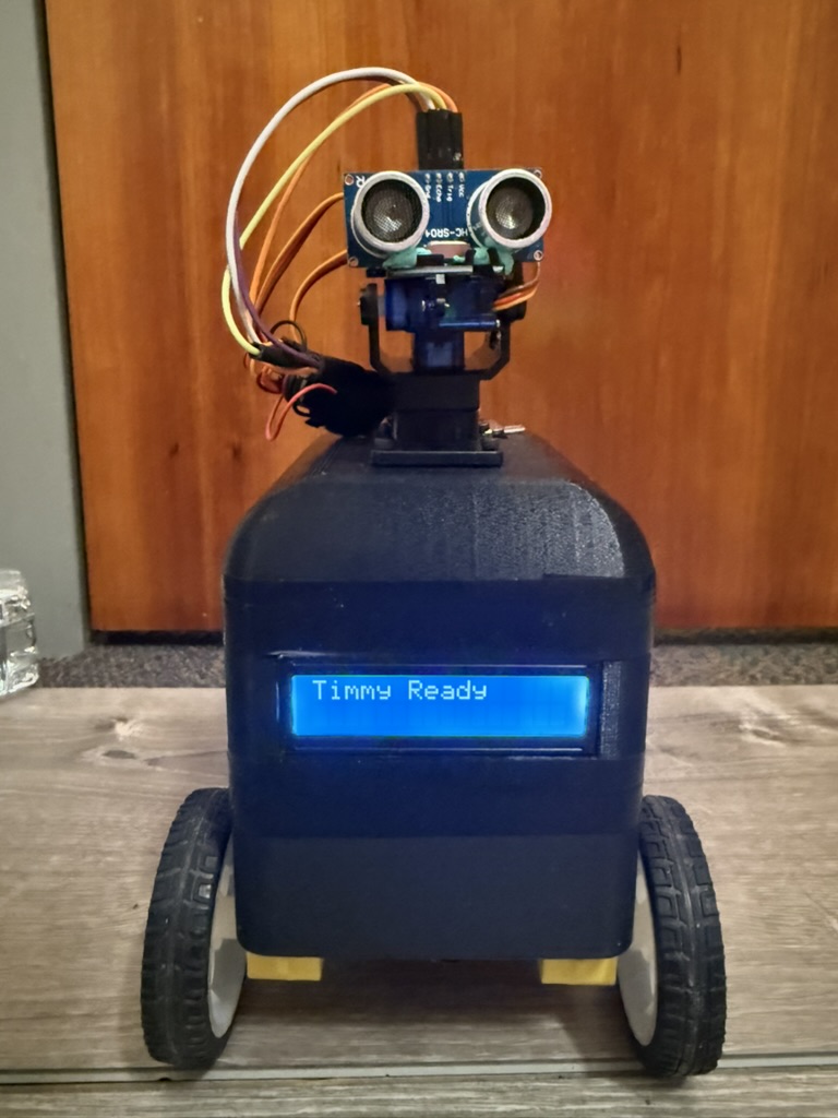
CodeBuddy Timmy Educational Robot
[Fall 2025] CodeBuddy Timmy is a Bluetooth-enabled educational robot that teaches robotics and programming through interactive play.
- Suitable forB.Tech/B.E Embedded Systems students
- Build time4-6 weeks
- LevelBeginner
- Available atAjvika Labs, Kakinada
About this project
Introduction
CodeBuddy Timmy is a Bluetooth-enabled educational robot that teaches robotics and programming through interactive play.
CodeBuddy Timmy is an interactive mobile robot designed to introduce students to core ideas in programming, embedded systems, and robotics. It brings together motors, sensors, a display, and sound into a friendly platform that responds in real time to both user input and its surroundings. Through a custom Bluetooth mobile app, users can wirelessly connect to Timmy to control how it moves, behaves, and switches between operating modes. Instead of acting like a simple remote-controlled toy, Timmy encourages hands-on exploration by letting users program behaviors and immediately see how their code affects the robot's motion and sensor responses.
The goal of this project is to make robotics more accessible to young learners by demonstrating how simple hardware and thoughtful software can create engaging educational robots.
High Level Design
Figure: High level overview of CodeBuddy Timmy robot
Project Rationale and Inspiration
CodeBuddy Timmy was inspired by educational robots like Dash, which show how movement, sound, and interaction can make robotics engaging for beginners. Many of these commercial robots, however, rely on proprietary hardware and software that hide how the system actually works. The goal of this project was to build a similar interactive experience using inexpensive, student-built hardware while keeping the design transparent and easy to understand. By doing so, the robot makes it clear how sensor data, control logic, and motor outputs work together to produce behavior.
Logical Structure
Timmy is built around a microcontroller that continuously reads sensor inputs, processes user commands, and drives the robot's actuators. Sensors provide information about the robot's environment, while outputs include DC motors, servos, an LCD, LEDs, and a buzzer. A Bluetooth connection links the robot to a custom mobile app, which serves as the primary user interface and enables wireless control in real time. In addition to direct manual control, the mobile app includes a programming mode that allows users to construct simple programs using visual coding blocks. Through this interface, young learners and other users can create loops, sequences, and conditional behaviors that iterate through different motions, sounds, and sensing actions. This feature bridges the gap between immediate interaction and structured programming, allowing users to experiment with control logic and observe how software decisions translate into physical robot behavior.
Figure: Timmy Block Diagram
The design of CodeBuddy Timmy focused on keeping the hardware simple while allowing flexibility in software. Implementing behavior logic in software allowed modes to be easily modified and extended as the project evolved. Bluetooth was used instead of a wired interface to improve usability and engagement. These tradeoffs were made to favor transparency and ease of learning over maximum performance.
Although our robot draws inspiration from existing educational robots, it does not replicate any proprietary hardware or software. We developed all system architecture, code, and mechanical designs specifically for this project using publicly available interfaces. The project is intended as an educational prototype and learning tool, not a commercial product.
No known patents, copyrights, or trademarks are directly applicable to this project, as all hardware designs and software were developed independently using publicly available components and reference materials for educational purposes.
Hardware Design
Figure: Schematic of the circuit
Chassis Design
We modeled the robot chassis in Onshape and fabricated it using 3D printing. It is designed as a three-layer three-layer stacked structure with press fit, allowing the parts to align securely while still being easily separated by subsystem. This mechanical separation directly mirrors the electrical architecture, physically isolating motor hardware from sensitive control and sensing components. As a result, the design improves modularity, reduces electrical noise coupling, and simplifies modification and troubleshooting.
Figure: 3D model of the robot chassis showing the three-layer structure
The bottom layer serves as the power and drive compartment. It has a custom-assembled dual-channel motor driver, a passive buzzer, and two battery packs for motor power. The bottom has openings for tabs that hold the two DC gear motors and wheels in place. This layer includes vertical wire pass-throughs that route motor control signals and power upward to the control electronics in the middle layer and to the DC motors themselves.
The middle layer has the control electronics and user-facing interfaces. A solderboard mounted in this layer supports the Raspberry Pi Pico and a BOOTSEL push button for programming and reset access. Another dedicated battery pack powers the Pico and all low-power peripherals in this layer. It also has a front-facing LCD display, making the robot's name, operating mode, and obstacle detection status visible.
The top layer is a domed lid. At the center of the dome is a pan-tilt servo assembly that holds the ultrasonic distance sensor, allowing it to actively scan the environment. A microphone module is mounted near the top of the robot to improve acoustic sensitivity while reducing the effects of mechanical vibration from the motors and drivetrain.
Electrical Isolation
The robot uses fully isolated power sources for the motors and logic electronics. Two battery packs located in the bottom layer supply power exclusively to the motor driver and DC motors. A completely separate battery pack in the middle layer powers the Raspberry Pi Pico and all low-power peripherals. The motor power system and the microcontroller power system do not share a common ground. This design choice was intentional and motivated by reliability, noise immunity, and safety considerations discussed in lecture. DC motors are electrically noisy loads. During startup, rapid speed changes, or stall conditions, they draw large transient currents and generate significant electrical noise and back-EMF. If motor and logic circuits share a ground reference, these disturbances can couple into sensitive electronics and cause unstable sensor readings, timing errors, communication issues, or unexpected resets.
Raspberry Pi Pico
The Raspberry Pi Pico serves as the central controller for the system. Since the Pico is the platform we have been working with throughout the course, it was the natural choice for implementing a project of this size and complexity. In this project, the Pico provides the GPIO, hardware PWM, ADC inputs, and I2C communication needed to interface with the robot's motors, sensors, and user interfaces.
Motor Driver and Motor
Figure: A picture of the custom motor board with L293D and 4N35 Opto isolators
The two DC gear motors are used for differential drive system, which allows the robot to move forward and backward, turn by running the wheels at different speeds, and rotate in place. Each motor is mounted to the bottom layer of the chassis using integrated 3D-printed tabs that hold the motor body securely and keep the shafts aligned with the wheels. This prevents the motors from shifting or twisting under load and ensures consistent, repeatable motion. Overall, the differential drive setup provides good maneuverability while staying mechanically simple and easy to control in software.
Motor control is implemented using a custom-built driver based on the L293D dual H-bridge motor driver IC. The Raspberry Pi Pico provides digital direction signals and PWM enable signals to the L293D, allowing independent control of motor direction and speed.
Early in development, the project aimed to include a self-balancing feature, which required precise, low-noise sensor measurements and tightly coupled motor control. During testing, the DC motors generated significant electrical noise and voltage spikes, especially during startup and rapid speed changes. When motor and logic electronics shared ground, this noise caused i2c to stall and the motors to run all full speed. To address this, optoisolators were added to the motor control signal paths, and the motor power system was kept electrically isolated from the logic power system using separate battery packs.
Audio Feedback
A passive piezoelectric buzzer is mounted in the bottom compartment and aligned with acoustic openings in the chassis. Unlike an active buzzer, it is driven directly by the Pico, which outputs square-wave signals at specific frequencies and durations using PWM. These signals cause the piezo element to vibrate, producing tones that indicate startup, mode changes, obstacle detection, and internal "thinking" states. Placing the buzzer in the bottom layer keeps wiring short while still allowing sound to propagate clearly through the enclosure.
Ultrasonic Sensor with Pan-Tilt Actuation
Figure: Operating principle of the HC-SR04 ultrasonic sensor showing transmitted and reflected sound waves used for distance measurement. Image source: HowToMechatronics (https://howtomechatronics.com)
Obstacle detection is handled by an HC-SR04 ultrasonic distance sensor mounted on a two-axis pan-tilt mechanism at the top of the robot. The Pico initiates a measurement by sending a 10 microsecond pulse on the trigger pin, causing the sensor to emit an ultrasonic signal. The echo pin then remains high for the time it takes the sound to travel to an object and reflect back. By measuring this duration and using the known speed of sound, the Pico calculates the distance to nearby obstacles.
The pan and tilt motion is controlled by two SG90 servo motors. The servos use a small DC motor, gearbox, feedback potentiometer, and control electronics to hold the shaft at the desired position. This setup allows the robot to actively scan its surroundings both ho
CodeBuddy Timmy is a Bluetooth-enabled educational robot that teaches robotics and programming through interactive play.
CodeBuddy Timmy is an interactive mobile robot designed to introduce students to core ideas in programming, embedded systems, and robotics. It brings together motors, sensors, a display, and sound into a friendly platform that responds in real time to both user input and its surroundings. Through a custom Bluetooth mobile app, users can wirelessly connect to Timmy to control how it moves, behaves, and switches between operating modes. Instead of acting like a simple remote-controlled toy, Timmy encourages hands-on exploration by letting users program behaviors and immediately see how their code affects the robot's motion and sensor responses.
The goal of this project is to make robotics more accessible to young learners by demonstrating how simple hardware and thoughtful software can create engaging educational robots.
High Level Design
Figure: High level overview of CodeBuddy Timmy robot
Project Rationale and Inspiration
CodeBuddy Timmy was inspired by educational robots like Dash, which show how movement, sound, and interaction can make robotics engaging for beginners. Many of these commercial robots, however, rely on proprietary hardware and software that hide how the system actually works. The goal of this project was to build a similar interactive experience using inexpensive, student-built hardware while keeping the design transparent and easy to understand. By doing so, the robot makes it clear how sensor data, control logic, and motor outputs work together to produce behavior.
Logical Structure
Timmy is built around a microcontroller that continuously reads sensor inputs, processes user commands, and drives the robot's actuators. Sensors provide information about the robot's environment, while outputs include DC motors, servos, an LCD, LEDs, and a buzzer. A Bluetooth connection links the robot to a custom mobile app, which serves as the primary user interface and enables wireless control in real time. In addition to direct manual control, the mobile app includes a programming mode that allows users to construct simple programs using visual coding blocks. Through this interface, young learners and other users can create loops, sequences, and conditional behaviors that iterate through different motions, sounds, and sensing actions. This feature bridges the gap between immediate interaction and structured programming, allowing users to experiment with control logic and observe how software decisions translate into physical robot behavior.
Figure: Timmy Block Diagram
The design of CodeBuddy Timmy focused on keeping the hardware simple while allowing flexibility in software. Implementing behavior logic in software allowed modes to be easily modified and extended as the project evolved. Bluetooth was used instead of a wired interface to improve usability and engagement. These tradeoffs were made to favor transparency and ease of learning over maximum performance.
Although our robot draws inspiration from existing educational robots, it does not replicate any proprietary hardware or software. We developed all system architecture, code, and mechanical designs specifically for this project using publicly available interfaces. The project is intended as an educational prototype and learning tool, not a commercial product.
No known patents, copyrights, or trademarks are directly applicable to this project, as all hardware designs and software were developed independently using publicly available components and reference materials for educational purposes.
Hardware Design
Figure: Schematic of the circuit
Chassis Design
We modeled the robot chassis in Onshape and fabricated it using 3D printing. It is designed as a three-layer three-layer stacked structure with press fit, allowing the parts to align securely while still being easily separated by subsystem. This mechanical separation directly mirrors the electrical architecture, physically isolating motor hardware from sensitive control and sensing components. As a result, the design improves modularity, reduces electrical noise coupling, and simplifies modification and troubleshooting.
Figure: 3D model of the robot chassis showing the three-layer structure
The bottom layer serves as the power and drive compartment. It has a custom-assembled dual-channel motor driver, a passive buzzer, and two battery packs for motor power. The bottom has openings for tabs that hold the two DC gear motors and wheels in place. This layer includes vertical wire pass-throughs that route motor control signals and power upward to the control electronics in the middle layer and to the DC motors themselves.
The middle layer has the control electronics and user-facing interfaces. A solderboard mounted in this layer supports the Raspberry Pi Pico and a BOOTSEL push button for programming and reset access. Another dedicated battery pack powers the Pico and all low-power peripherals in this layer. It also has a front-facing LCD display, making the robot's name, operating mode, and obstacle detection status visible.
The top layer is a domed lid. At the center of the dome is a pan-tilt servo assembly that holds the ultrasonic distance sensor, allowing it to actively scan the environment. A microphone module is mounted near the top of the robot to improve acoustic sensitivity while reducing the effects of mechanical vibration from the motors and drivetrain.
Electrical Isolation
The robot uses fully isolated power sources for the motors and logic electronics. Two battery packs located in the bottom layer supply power exclusively to the motor driver and DC motors. A completely separate battery pack in the middle layer powers the Raspberry Pi Pico and all low-power peripherals. The motor power system and the microcontroller power system do not share a common ground. This design choice was intentional and motivated by reliability, noise immunity, and safety considerations discussed in lecture. DC motors are electrically noisy loads. During startup, rapid speed changes, or stall conditions, they draw large transient currents and generate significant electrical noise and back-EMF. If motor and logic circuits share a ground reference, these disturbances can couple into sensitive electronics and cause unstable sensor readings, timing errors, communication issues, or unexpected resets.
Raspberry Pi Pico
The Raspberry Pi Pico serves as the central controller for the system. Since the Pico is the platform we have been working with throughout the course, it was the natural choice for implementing a project of this size and complexity. In this project, the Pico provides the GPIO, hardware PWM, ADC inputs, and I2C communication needed to interface with the robot's motors, sensors, and user interfaces.
Motor Driver and Motor
Figure: A picture of the custom motor board with L293D and 4N35 Opto isolators
The two DC gear motors are used for differential drive system, which allows the robot to move forward and backward, turn by running the wheels at different speeds, and rotate in place. Each motor is mounted to the bottom layer of the chassis using integrated 3D-printed tabs that hold the motor body securely and keep the shafts aligned with the wheels. This prevents the motors from shifting or twisting under load and ensures consistent, repeatable motion. Overall, the differential drive setup provides good maneuverability while staying mechanically simple and easy to control in software.
Motor control is implemented using a custom-built driver based on the L293D dual H-bridge motor driver IC. The Raspberry Pi Pico provides digital direction signals and PWM enable signals to the L293D, allowing independent control of motor direction and speed.
Early in development, the project aimed to include a self-balancing feature, which required precise, low-noise sensor measurements and tightly coupled motor control. During testing, the DC motors generated significant electrical noise and voltage spikes, especially during startup and rapid speed changes. When motor and logic electronics shared ground, this noise caused i2c to stall and the motors to run all full speed. To address this, optoisolators were added to the motor control signal paths, and the motor power system was kept electrically isolated from the logic power system using separate battery packs.
Audio Feedback
A passive piezoelectric buzzer is mounted in the bottom compartment and aligned with acoustic openings in the chassis. Unlike an active buzzer, it is driven directly by the Pico, which outputs square-wave signals at specific frequencies and durations using PWM. These signals cause the piezo element to vibrate, producing tones that indicate startup, mode changes, obstacle detection, and internal "thinking" states. Placing the buzzer in the bottom layer keeps wiring short while still allowing sound to propagate clearly through the enclosure.
Ultrasonic Sensor with Pan-Tilt Actuation
Figure: Operating principle of the HC-SR04 ultrasonic sensor showing transmitted and reflected sound waves used for distance measurement. Image source: HowToMechatronics (https://howtomechatronics.com)
Obstacle detection is handled by an HC-SR04 ultrasonic distance sensor mounted on a two-axis pan-tilt mechanism at the top of the robot. The Pico initiates a measurement by sending a 10 microsecond pulse on the trigger pin, causing the sensor to emit an ultrasonic signal. The echo pin then remains high for the time it takes the sound to travel to an object and reflect back. By measuring this duration and using the known speed of sound, the Pico calculates the distance to nearby obstacles.
The pan and tilt motion is controlled by two SG90 servo motors. The servos use a small DC motor, gearbox, feedback potentiometer, and control electronics to hold the shaft at the desired position. This setup allows the robot to actively scan its surroundings both ho
Technologies used
Hardware components
- Raspberry Pi Pico
- LCD
- servo motor
- DC motor
- IMU
- ultrasonic sensor
- microphone
- ADC
- H-bridge
- motor driver
Software & tools
- C
- Arduino IDE
Project demo video
What you get
- Working project / hardware kit, tested before delivery
- Complete source code with explanation
- Project demo and guidance for your viva
- Project report, PPT and IEEE paper support (on request)
Delivery & Payment
Delivery takes a minimum of two weeks from the date your inquiry is confirmed.
Payment is in two parts:
• 50% advance to start the project
• Remaining 50% before delivery
Note:
• Documentation and PPT are not included by default
• If you need documentation/PPT, it can be arranged for extra time and cost
We'll confirm the exact timeline and cost with you after reviewing your requirements.
Related Embedded Systems projects

Embedded Systems
Gas Leakage Detector Using Arduino
A budget-friendly LPG gas leak detector built with an Arduino and MQ-5 gas sensor, triggering a buzzer and LED when unsafe gas levels are de...
View project
Embedded Systems
Simple Alarm System
A beginner-friendly home alarm with PIR motion sensing, keypad PIN entry, and separate entry/exit timing delays, built to be easy to expand.
View project
Embedded Systems
Ultrasonic Sensor Project with Arduino UNO Q
A beginner-friendly first Arduino UNO Q project: a servo-swept ultrasonic sensor that renders a live sweeping radar display in a web browser...
View project
Embedded Systems
3D Audio Localization
[Fall 2025] We designed a real-time embedded system that localizes sound sources in three dimensions and visualizes them live using a four-m...
View project