Ball balancing robot Spring 2025
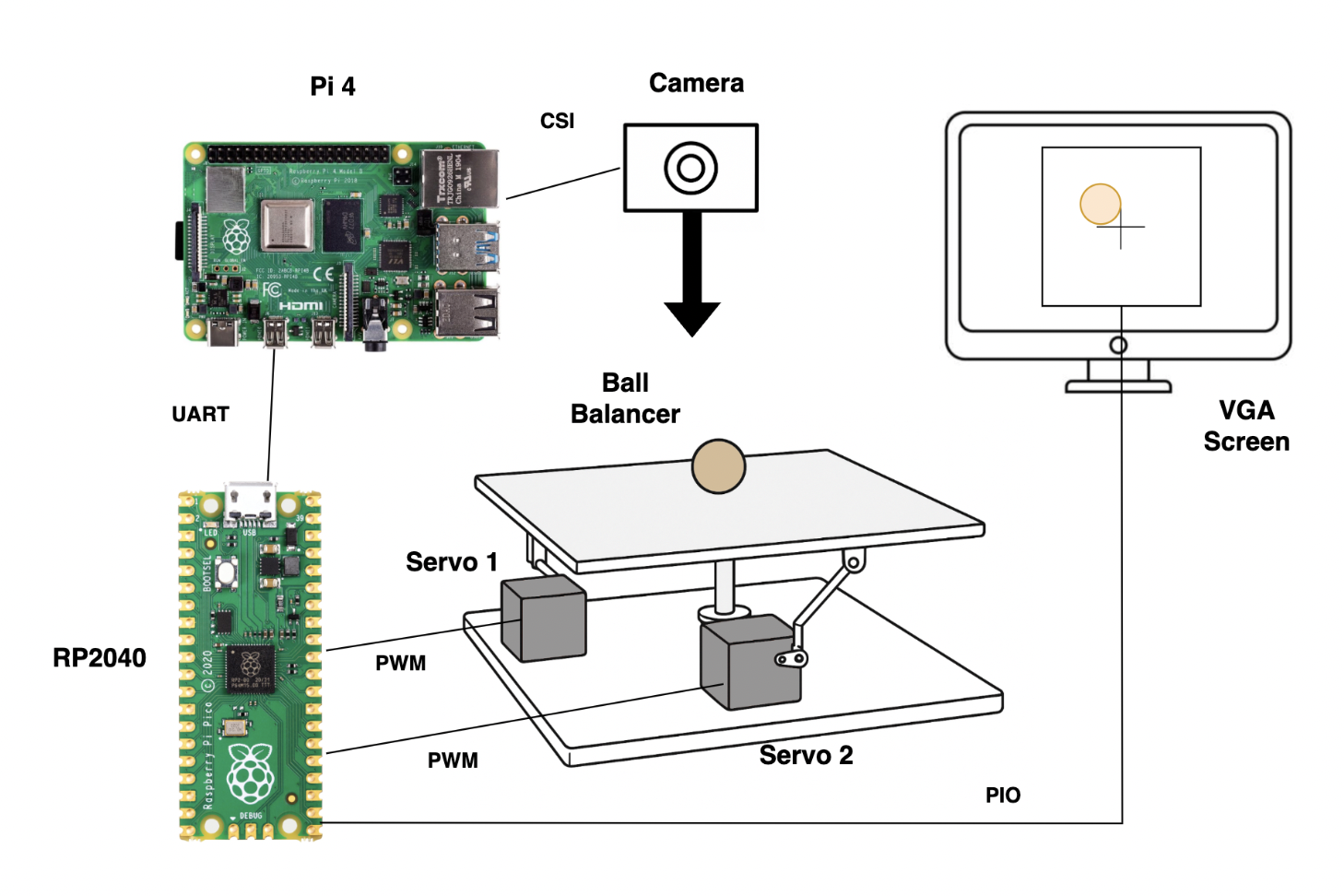
[Spring 2025] This project implements a real-time ball balancing system using a single-camera vision setup and a two-axis tilting platform, controlled with a Raspberry Pi 4 and RP2040 microcontroller. Our project aimed to develop a ball balancing system that uses a top-mounted camera to track the 2D position of a ball on a tilting platform. The Raspberry Pi 4 handles image processing and position tracking, while we communicate the position to the RP2040 which
- Suitable forB.Tech/B.E Embedded Systems students
- Build time4-6 weeks
- LevelBeginner
- Available atAjvika Labs, Kakinada
About this project
This project implements a real-time ball balancing system using a
single-camera vision setup and a two-axis tilting platform, controlled
with a Raspberry Pi 4 and RP2040 microcontroller. Our project aimed to
develop a ball balancing system that uses a top-mounted camera to track
the 2D position of a ball on a tilting platform. The Raspberry Pi 4
handles image processing and position tracking, while we communicate the
position to the RP2040 which controls the platform's tilt using two
servos driven by PWM signals. The ball's position is continuously
adjusted using a closed-loop PID controller to stabilize it at the
center or balanced at a target position we can set. This project
demonstrates real-time feedback control and image processing techniques,
combining mechanical designs, software algorithms, and low-level
hardware control.
Demo Video
Below is the link to our Project Demo Video:
High-Level Design
We wanted to build something physical and expand on our previous work in
the class implementing a PID controller for a one-degree-of-freedom
helicopter. Throughout development, we introduced several simplifying
assumptions to keep our implementation tractable while still capturing
the system’s behavior. By constraining the platform tilt to ±10°, we
applied the small-angle approximation (sin θ ≈ θ) to linearize
gravitational torque into a simple proportional term. Instead of
deriving a full forward-kinematic model for the servo linkages, we swept
each servo through its range, measured the resulting platform angles
with a digital level, and observed an approximately linear mapping
between PWM input and tilt. To further enhance stability, we mounted the
servo horns at the platform’s outer edge so that small servo-angle
adjustments produce correspondingly smaller angular responses, reducing
high-frequency jitter. Finally, we ignored secondary dynamics such as
joint friction (mitigated by our ball bearings), since these effects
were negligible compared to the dominant gravitational and inertial
forces.
We mounted a USB camera directly above the platform to provide a
continuous top-down view of the ball. The camera plugs into the
Raspberry Pi’s USB port, where we leverage OpenCV libraries to capture
each frame and apply color threshold-based processing to isolate the
ball’s center. Once we compute the ball’s x and y pixel coordinates, we
package them into a simple data string and stream it over UART to the
RP2040 for real-time control. Our vision loop runs at 30 Hz, which
provides more than enough bandwidth for this task given the ball’s
relatively high inertia and slow dynamics.
On the RP2040, multiple threads handle distinct tasks: a parser thread
processes incoming position data, a control thread runs the PID
algorithm and updates each servo’s PWM output, and a VGA thread redraws
live feedback, plotting error terms and the ball’s real-time position on
screen so we can visualize how those errors affect our control of the
system.
System block diagram
Program/hardware design
Full Project
Ball Tracking
Our ball-tracking script on the Raspberry Pi is organized into three
parts: camera capture, ball detection, and UART transmission. In the
camera capture stage, we initialize the USB camera on the Pi's USB port
and enter a continuous loop to grab each raw frame. To speed up the
image processing, we immediately resize every frame to 320x240 pixels.
It wasn't necesay to use the full resolution to track the ball's
position and this also reduces compute time for masks and contour
calculations. During ball detection each frame is passed to the
detect_ball function. Inside the detect_ball function, we apply a
gaussian blur to reduce sensor noise and then convert the result to HSV
color space. We threshold on a calibrated orange range to produce a
binary mask and clean it with morphological open and close operations so
the ball appears as a solid blob as shown below.
Binary Ball Tracking
After converting to a binary image, we call cv2.findContours() to
extract all contours, select the largest one, and fit a minimum
enclosing circle around it. If the detected radius exceeds our 10-pixel
threshold, we assume it's the ball and return its (x, y, radius) tuple;
otherwise, detect_ball returns None. Below, you can see the result
overlaid with the detected circle and an arrow pointing to the
platform's center. Initially, we wrote a script to compute the exact
center dynamically, but found that tilting the platform didn't shift it
enough to matter. Since the camera is mounted directly above the
platform's center, we hard-coded the center as a black cross to
eliminate random shifts and save extra computation on the Raspberry Pi.
Ball Tracking
In the UART transmission stage, the main loop checks whether detect_ball
found a valid circle. When it does, we format the ball's pixel
coordinates as a string (x,y) and send it over serial to the RP2040.
This enables our microcontroller to respond to the ball's position in
real time. We run the entire pipeline at 30 Hz, which is sufficient
given the ball's relatively high inertia and the dynamic response of our
balancing platform.
UART communication
The UART communication between the Raspberry Pi 4 and the RP2040 is a
critical component of our project, enabling real-time data exchange for
precise platform control. The RP2040, responsible for controlling the
servos, receives continuous updates about the ball’s position from the
Raspberry Pi. This data link is established using a UART connection,
configured at a baud rate of 115200 bps, which we found to be a good
balance between speed and data integrity. The physical wiring connects
the RP2040’s UART1 interface, using GPIO 8 for transmission (TX) and
GPIO 9 for reception (RX), with the corresponding UART pins on the
Raspberry Pi. Proper grounding between the two devices was also
essential to prevent signal noise and data corruption.
On the RP2040, the UART communication is managed through a protothread
that constantly monitors incoming data. This thread reads each character
from the UART buffer, looking for complete coordinate messages formatted
as (x,y). Once a message is detected, it is parsed and smoothed using an
exponential moving average to reduce jitter. The smoothing process uses
a formula like smoothed_x = 0.4 * smoothed_x + 0.6 * num1, which
balances stability and responsiveness. The resulting smoothed
coordinates are then used to compute the position error relative to the
platform’s center, clamped within a range of -80 to 80 to prevent
overextension of the servos.
On the Raspberry Pi, the corresponding Python code uses a simple
function to send the (x,y) data over UART. This function formats the
message as a string before transmission, ensuring compatibility with the
RP2040’s parser. Early versions of this code faced challenges with
buffer overflows and signal noise, but these were resolved through
careful tuning of the buffer size and smoothing parameters. Overall,
this communication setup provides a stable and responsive link between
the image processing and platform control components of our system.
System Wiring
Balancer Platform
We built the entire tilting platform from 3D-printed parts, assembled
with screws and ball bearings, all anchored to a wooden base plate. The
entire platform and the servo mounts were designed using Onshape CAD
software. We assembled all the pieces and tested the structure’s motion
in software first to minimize the number of reprints. For the pivot
mechanism, we took inspiration from an existing design but upgraded it
with ball bearings to achieve smooth rotation across all degrees of
freedom. The 3D-printed tilt assembly is screwed directly to the wood,
and a simple wooden structure holds the camera directly over the
platform’s center for top-down view. We 3D-printed servo holders so we
could screw the servos in place and then printed lever arms to connect
the balancing platform to the servo. The lever arm attaches to the servo
via a male connector with a screw hole, as shown below. 3D printing
allowed us to rapidly prototype and create a simple structure that
tilted with low friction. Finally, we chose a bright green mat and a
contrasting orange ball to simplify color-based segmentation, making our
vision pipeline both fast and reliable.
Ball platform Design
Balancer PID Servo control
The PID control system is the core of our platform’s stabilization
mechanism, converting the ball’s position error into precise servo
commands that adjust the platform’s tilt. This approach allows the
system to rapidly and accurately respond to changes in the ball’s
position, keeping it centered even as it moves dynamically. The RP2040
microcontroller manages this process, using a pair of PWM channels to
drive the two servos that control the platform’s pitch and roll.
The servos are driven using pulse-width modulation (PWM) signals, which
the RP2040 generates with a fixed frequency of 50Hz, the standard for
most hobbyist servos. This frequency was chosen because it matches the
servo’s expected control rate, providing consistent and smooth motion.
The PWM duty cycle, which directly controls the servo angle, is
calculated using the angle_to_level function. This function maps the
desired ang
Technologies used
Hardware components
- RP2040
- IMU
Software & tools
- Python
Project demo video
What you get
- Working project / hardware kit, tested before delivery
- Complete source code with explanation
- Project demo and guidance for your viva
- Project report, PPT and IEEE paper support (on request)
Related Embedded Systems projects

Gas Leakage Detector Using Arduino
A budget-friendly LPG gas leak detector built with an Arduino and MQ-5 gas sensor, triggering a buzzer and LED when unsafe gas levels are de...
View project
Simple Alarm System
A beginner-friendly home alarm with PIR motion sensing, keypad PIN entry, and separate entry/exit timing delays, built to be easy to expand.
View project
Ultrasonic Sensor Project with Arduino UNO Q
A beginner-friendly first Arduino UNO Q project: a servo-swept ultrasonic sensor that renders a live sweeping radar display in a web browser...
View project
3D Audio Localization
[Fall 2025] We designed a real-time embedded system that localizes sound sources in three dimensions and visualizes them live using a four-m...
View project