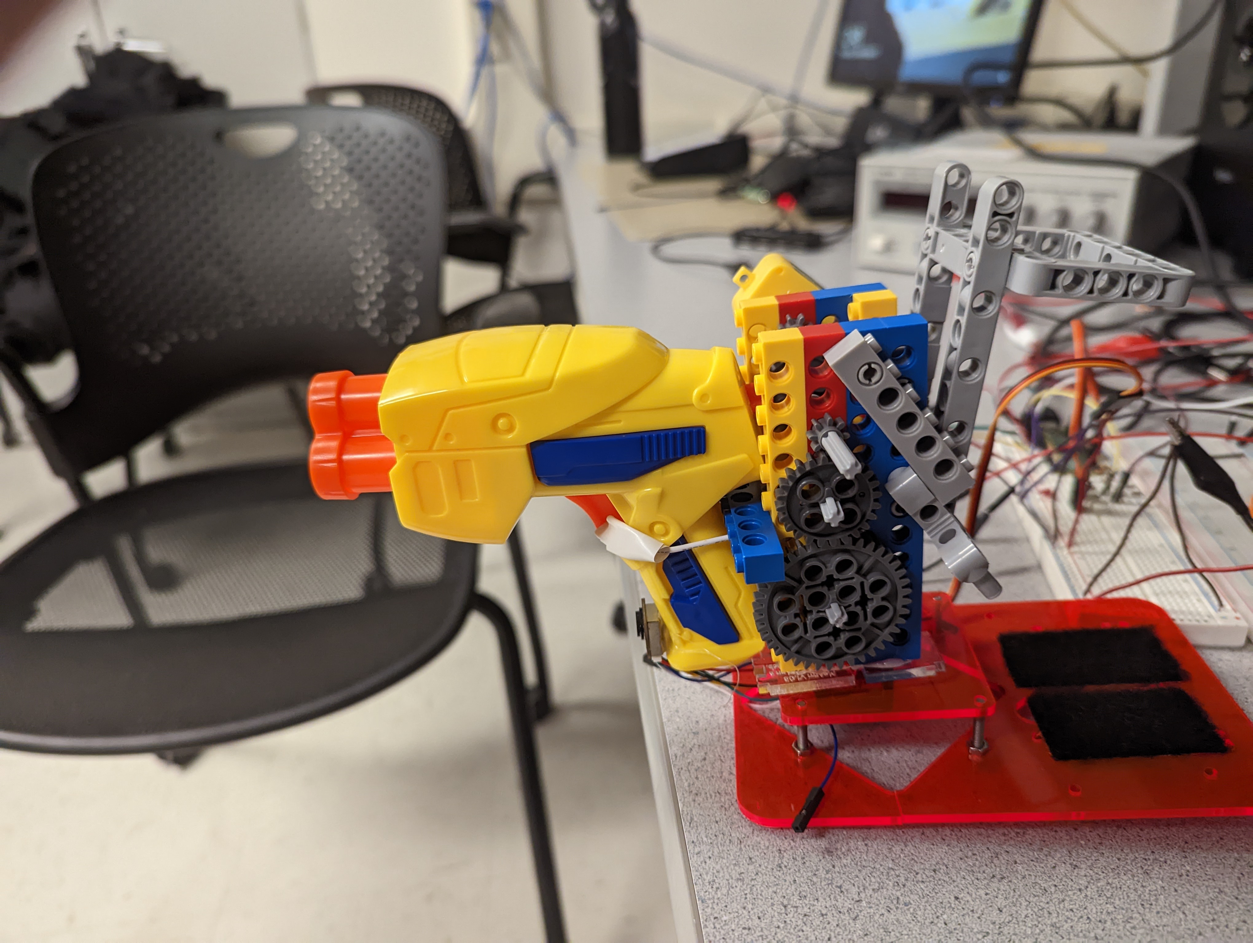
Auto-targeting Nerf gun
[Fall 2022] The purpose of this project was to create an auto-targeting nerf gun using various motors and sensors
- Suitable forB.Tech/B.E Embedded Systems students
- Build time4-6 weeks
- LevelBeginner
- Available atAjvika Labs, Kakinada
About this project
Final Report
Project Introduction
The purpose of this project was to create an auto-targeting nerf gun using various motors and sensors
This project integrates an RP2040, servo, DC motor, time-of-flight sensor, nerf gun, and other miscellaneous hardware to accomplish the completion of an auto-targeting nerf gun. The reason this project was chosen was because we wanted to create a fun project that gave us insight on how to integrate a variety of different hardware devices. As a quick summary, the turret sweeps an area of about 180 degrees, finds a target object, locks on, and “shoots.”
High level design
The main rationale for the project was that we wanted to integrate multiple hardware devices to create something fun. Given that we had a tiny Nerf gun, we concluded that we had a great opportunity to integrate a variety of sensors, servos, and motors by creating an auto-targeting system.
Figure 1: High Level Diagram
Figure 1 above gives a general overview of how the system works. The turret sweeps back and forth within a certain range (i.e., -90 degrees to 90 degrees), captures the edges of the target, and then centers on the object through a simple averaging function. This is when the trigger for the turret is pulled. Besides this, there was no basic background math that had to be involved. The structure of the project included implementing each hardware device independently and then integrating onto the final product. For example, the time-of-flight sensor was implemented independently of everything else and then interfaced with the rest of the system later. This helped the process of implementation because if there was trouble implementing one device, it didn’t necessarily interfere with the implementation of everything else.
Since this design included a somewhat complicated hardware design, there were some tradeoffs that had to be considered. The complexity of the hardware that was implemented produced some serious physical constraints on the system. For example, the motor to pull the trigger had to go through a gear ratio to produce enough torque to pull the trigger. Secondly, the size of the gun and trigger mechanism, along with the somewhat slow speed of the time-of-flight sensor, limited the maximum speed at which the servo could sweep. These were just some of the tradeoffs that had to be dealt with during implementation.
Besides the copyrights to the individual devices (Nerf gun, servo, Lego-bricks, time-of-flight sensor), there were no existing patents, copyrights, or trademarks that had to be considered.
Program/hardware design
Circuit
Figure 2: Hardware Diagram
As can be seen, various elements go into this devices circuit. First is the time of flight sensor which has a pinout according to figure 3
Figure 3: TOF10120 pinout, screenshot from reference (2)
As later discussed, we used the UART interface, so SCL and SDA were not connected to the pico, but as can bee seen from figure 2, TX and RX are connected to gpio pins and VCC and ground are connected to their respective lines. We also had to hookup buttons to gpio pins. We used 10K resistors to pull down these buttons because at 3.3V, this was a standard pulldown resistor value. The buttons' inputs were tied to VCC and the outputs tied to gpio inputs thus only going high when pressed. Next, we hooked up the servo motor controlling our gun's platform. This was assigned according to figure 7 later in the document. Finally the h-bridge which controls the DC motor pulling the trigger mechanism was connected according to figure 4,
Figure 4: l293 pinout, screenshot from reference (4)
To connect this to the circuit, 'Y' represents an output, 'A' represents an input, and 'EN' represents enable. Because of this, we tied 4A and 3A to our 'forward' pwm channel and 'backward' pwm channel respectively. We then connected the inputs of the motor to the outputs of the h-bridge, the direction depending on which way we wanted the motor to move. The enable pin was set to VCC as the motor needed to be available at all times and if we needed the motor to stop, we could simply use a 0% duty cycle for both input pwm signals.
As can be seen, the two breadboards in the circuit have different voltages. Most of the devices we used could operate at 3.3V, but the motor needed its own power supply at 7V in order to provide the power needed for the motor to pull the nerf gun's trigger. Unlike Lab3, we did not use 4N35 chips as the communication between the laser sensor and pico was robust enough that noise from the motor did not cause a problem to the circuit.
Program Organization
The first consideration of the program was the file structure. It was decided that a main.h header file would be included using all possibly necessary libraries for completing the project. This would also be where the gpio pin layout and pin macros would be defined in order for a reader to understand what each pin does just by looking at the main header file. Since sensor data collection was a simply blackbox function, methods associated with it were placed in the laser.c file in order keep the main.c size small.
The next consideration was what tasks the main function had to complete. There were three processes that the program had to run. It had to run a process to collect data from our distance sensor to gather data on the object, it had to interpret this data and adjust the servo motor moving the platform accordingly. The third process which was useful for debugging was a serial interface which would print out the state of various important variables. Since these processes were sharing memory such as the distance variable, these processes were divided up as 3 protothreads.
Sensors
The first protothread, protothread_laser, would gather data from our laser sensor. This enters the discussion of the methods in laser.c.
A few considerations had to be made with the TOF1012. The device has two communication ports attached to it, an i2c channel and a UART channel, so we had to decide which method to use. The i2c channel did not seem to operate correctly as there was no functional address that i2c messages could be sent to that would make the sensor function, so we used the UART channel.
To communicate with the laser sensor over UART, we first initialized the UART1 channel of the pico with laser_init() as the UART0 channel was used for communication with our computer. uart_init() was used with a baud rate of 115200. This was checked by connecting the sensor directly to the computer and opening up a serial terminal. We adjusted the baud rate until ascii characters appeared in the terminal. We then had to configure our TX and RX pins to UART using gpio_set_func(). After this initialization method completed we would read sensor data using laser_read(). This utilized the fact that the sensor simply sent a stream of messages in the form " , Range Valid\n\nd: (distance) mm". We read the message using uart_read_blocking() with a buffer of size 100 as the message would surely never get more than 100 bytes long. We wanted to capture the distance variable, so we simply used the scanf function or sscanf function since we wanted this data in a distance variable, so we used the line
sscanf(buf," , Range Valid\n\nd: %d mm",distance);
where 'distance' was the integer we would stick the distance value into. We chose an integer since the sensor would only print integer values within a range of less than 10000, so a short could have been used instead, but the program was not resource intensive, so this was skipped.
One problem we had with this function was that when the distance value suddenly got larger, the distance value would stay at whatever value it had previously been at. We found that the reason for this was that sscanf was failing. This is because when a large data value was captured from the laser it would send "Read Fail", so since this string was not in the form our sscanf function was expecting, sscanf would fail thus not updating distance. To fix this, we checked if this fail message had been sent using strstr which checks if one string contains another substring within it, so if this string was sent to the pico, then a large data value had been recorded, so we would set distance to 10,000 as that would be much larger than the range we want to shoot at objects inside of. So this assignment was based on
strstr(buf, "Fail") != NULL
which tells if "Fail" was in the message. If not, we would just read the distance value as we had done previously.
Currently we use a laser sensor, but we originally used an ultrasonic sensor. As opposed to the laser sensor, the ultrasonic sensor was connected in this pinout,
Figure 5: HC-SR04 pinout, screenshot from reference (3)
with trigger being an output gpio from the pico and echo being an input pin. To operate this sensor we followed both the tutorial at reference (5), but mostly relied on this figure
Figure 6: HC-SR04 operation description, screenshot from reference (3)
As can be seen from this figure, to gather a distance, we had to send a trigger pulse for 10 microseconds on the trigger pin, then wait until the echo pin went high and then base the distance off of how long the echo pin stays high. To do this, we used the hardware_gpio library to create input and output gpio pins for the trigger and echo pins respectively. Then, we used the PT_YIELD_usec() method to count microseconds. Therefore, we'd do
gpio_put(trigger,1);
PT_YIELD_usec(10);
gpio_put(trigger,0);
cnt = 0;
if(gpio_get(echo)){
while(gpio_get(echo)){
cnt++;
PT_YIELD_usec(1);
}
}
This yielded us a cnt variable corresponding to the distance recorded by the ultrasonic sensor. One issue with this was that cnt was relative and not an absolute distance. There was no problem though as all of our distances were relative, we could change the yield time inbetween increases of cnt in order to make far recorded distances h
Project Introduction
The purpose of this project was to create an auto-targeting nerf gun using various motors and sensors
This project integrates an RP2040, servo, DC motor, time-of-flight sensor, nerf gun, and other miscellaneous hardware to accomplish the completion of an auto-targeting nerf gun. The reason this project was chosen was because we wanted to create a fun project that gave us insight on how to integrate a variety of different hardware devices. As a quick summary, the turret sweeps an area of about 180 degrees, finds a target object, locks on, and “shoots.”
High level design
The main rationale for the project was that we wanted to integrate multiple hardware devices to create something fun. Given that we had a tiny Nerf gun, we concluded that we had a great opportunity to integrate a variety of sensors, servos, and motors by creating an auto-targeting system.
Figure 1: High Level Diagram
Figure 1 above gives a general overview of how the system works. The turret sweeps back and forth within a certain range (i.e., -90 degrees to 90 degrees), captures the edges of the target, and then centers on the object through a simple averaging function. This is when the trigger for the turret is pulled. Besides this, there was no basic background math that had to be involved. The structure of the project included implementing each hardware device independently and then integrating onto the final product. For example, the time-of-flight sensor was implemented independently of everything else and then interfaced with the rest of the system later. This helped the process of implementation because if there was trouble implementing one device, it didn’t necessarily interfere with the implementation of everything else.
Since this design included a somewhat complicated hardware design, there were some tradeoffs that had to be considered. The complexity of the hardware that was implemented produced some serious physical constraints on the system. For example, the motor to pull the trigger had to go through a gear ratio to produce enough torque to pull the trigger. Secondly, the size of the gun and trigger mechanism, along with the somewhat slow speed of the time-of-flight sensor, limited the maximum speed at which the servo could sweep. These were just some of the tradeoffs that had to be dealt with during implementation.
Besides the copyrights to the individual devices (Nerf gun, servo, Lego-bricks, time-of-flight sensor), there were no existing patents, copyrights, or trademarks that had to be considered.
Program/hardware design
Circuit
Figure 2: Hardware Diagram
As can be seen, various elements go into this devices circuit. First is the time of flight sensor which has a pinout according to figure 3
Figure 3: TOF10120 pinout, screenshot from reference (2)
As later discussed, we used the UART interface, so SCL and SDA were not connected to the pico, but as can bee seen from figure 2, TX and RX are connected to gpio pins and VCC and ground are connected to their respective lines. We also had to hookup buttons to gpio pins. We used 10K resistors to pull down these buttons because at 3.3V, this was a standard pulldown resistor value. The buttons' inputs were tied to VCC and the outputs tied to gpio inputs thus only going high when pressed. Next, we hooked up the servo motor controlling our gun's platform. This was assigned according to figure 7 later in the document. Finally the h-bridge which controls the DC motor pulling the trigger mechanism was connected according to figure 4,
Figure 4: l293 pinout, screenshot from reference (4)
To connect this to the circuit, 'Y' represents an output, 'A' represents an input, and 'EN' represents enable. Because of this, we tied 4A and 3A to our 'forward' pwm channel and 'backward' pwm channel respectively. We then connected the inputs of the motor to the outputs of the h-bridge, the direction depending on which way we wanted the motor to move. The enable pin was set to VCC as the motor needed to be available at all times and if we needed the motor to stop, we could simply use a 0% duty cycle for both input pwm signals.
As can be seen, the two breadboards in the circuit have different voltages. Most of the devices we used could operate at 3.3V, but the motor needed its own power supply at 7V in order to provide the power needed for the motor to pull the nerf gun's trigger. Unlike Lab3, we did not use 4N35 chips as the communication between the laser sensor and pico was robust enough that noise from the motor did not cause a problem to the circuit.
Program Organization
The first consideration of the program was the file structure. It was decided that a main.h header file would be included using all possibly necessary libraries for completing the project. This would also be where the gpio pin layout and pin macros would be defined in order for a reader to understand what each pin does just by looking at the main header file. Since sensor data collection was a simply blackbox function, methods associated with it were placed in the laser.c file in order keep the main.c size small.
The next consideration was what tasks the main function had to complete. There were three processes that the program had to run. It had to run a process to collect data from our distance sensor to gather data on the object, it had to interpret this data and adjust the servo motor moving the platform accordingly. The third process which was useful for debugging was a serial interface which would print out the state of various important variables. Since these processes were sharing memory such as the distance variable, these processes were divided up as 3 protothreads.
Sensors
The first protothread, protothread_laser, would gather data from our laser sensor. This enters the discussion of the methods in laser.c.
A few considerations had to be made with the TOF1012. The device has two communication ports attached to it, an i2c channel and a UART channel, so we had to decide which method to use. The i2c channel did not seem to operate correctly as there was no functional address that i2c messages could be sent to that would make the sensor function, so we used the UART channel.
To communicate with the laser sensor over UART, we first initialized the UART1 channel of the pico with laser_init() as the UART0 channel was used for communication with our computer. uart_init() was used with a baud rate of 115200. This was checked by connecting the sensor directly to the computer and opening up a serial terminal. We adjusted the baud rate until ascii characters appeared in the terminal. We then had to configure our TX and RX pins to UART using gpio_set_func(). After this initialization method completed we would read sensor data using laser_read(). This utilized the fact that the sensor simply sent a stream of messages in the form " , Range Valid\n\nd: (distance) mm". We read the message using uart_read_blocking() with a buffer of size 100 as the message would surely never get more than 100 bytes long. We wanted to capture the distance variable, so we simply used the scanf function or sscanf function since we wanted this data in a distance variable, so we used the line
sscanf(buf," , Range Valid\n\nd: %d mm",distance);
where 'distance' was the integer we would stick the distance value into. We chose an integer since the sensor would only print integer values within a range of less than 10000, so a short could have been used instead, but the program was not resource intensive, so this was skipped.
One problem we had with this function was that when the distance value suddenly got larger, the distance value would stay at whatever value it had previously been at. We found that the reason for this was that sscanf was failing. This is because when a large data value was captured from the laser it would send "Read Fail", so since this string was not in the form our sscanf function was expecting, sscanf would fail thus not updating distance. To fix this, we checked if this fail message had been sent using strstr which checks if one string contains another substring within it, so if this string was sent to the pico, then a large data value had been recorded, so we would set distance to 10,000 as that would be much larger than the range we want to shoot at objects inside of. So this assignment was based on
strstr(buf, "Fail") != NULL
which tells if "Fail" was in the message. If not, we would just read the distance value as we had done previously.
Currently we use a laser sensor, but we originally used an ultrasonic sensor. As opposed to the laser sensor, the ultrasonic sensor was connected in this pinout,
Figure 5: HC-SR04 pinout, screenshot from reference (3)
with trigger being an output gpio from the pico and echo being an input pin. To operate this sensor we followed both the tutorial at reference (5), but mostly relied on this figure
Figure 6: HC-SR04 operation description, screenshot from reference (3)
As can be seen from this figure, to gather a distance, we had to send a trigger pulse for 10 microseconds on the trigger pin, then wait until the echo pin went high and then base the distance off of how long the echo pin stays high. To do this, we used the hardware_gpio library to create input and output gpio pins for the trigger and echo pins respectively. Then, we used the PT_YIELD_usec() method to count microseconds. Therefore, we'd do
gpio_put(trigger,1);
PT_YIELD_usec(10);
gpio_put(trigger,0);
cnt = 0;
if(gpio_get(echo)){
while(gpio_get(echo)){
cnt++;
PT_YIELD_usec(1);
}
}
This yielded us a cnt variable corresponding to the distance recorded by the ultrasonic sensor. One issue with this was that cnt was relative and not an absolute distance. There was no problem though as all of our distances were relative, we could change the yield time inbetween increases of cnt in order to make far recorded distances h
Technologies used
Hardware components
- RP2040
- servo motor
- DC motor
- IMU
- ultrasonic sensor
- H-bridge
Software & tools
- C
- Arduino IDE
Project demo video
What you get
- Working project / hardware kit, tested before delivery
- Complete source code with explanation
- Project demo and guidance for your viva
- Project report, PPT and IEEE paper support (on request)
Delivery & Payment
Delivery takes a minimum of two weeks from the date your inquiry is confirmed.
Payment is in two parts:
• 50% advance to start the project
• Remaining 50% before delivery
Note:
• Documentation and PPT are not included by default
• If you need documentation/PPT, it can be arranged for extra time and cost
We'll confirm the exact timeline and cost with you after reviewing your requirements.
Related Embedded Systems projects

Embedded Systems
Gas Leakage Detector Using Arduino
A budget-friendly LPG gas leak detector built with an Arduino and MQ-5 gas sensor, triggering a buzzer and LED when unsafe gas levels are de...
View project
Embedded Systems
Simple Alarm System
A beginner-friendly home alarm with PIR motion sensing, keypad PIN entry, and separate entry/exit timing delays, built to be easy to expand.
View project
Embedded Systems
Ultrasonic Sensor Project with Arduino UNO Q
A beginner-friendly first Arduino UNO Q project: a servo-swept ultrasonic sensor that renders a live sweeping radar display in a web browser...
View project
Embedded Systems
3D Audio Localization
[Fall 2025] We designed a real-time embedded system that localizes sound sources in three dimensions and visualizes them live using a four-m...
View project