Audio tracking with soundar
[Fall 2023] Sound Bite:Our project was a soundar, that allowed us to pinpoint any sound that was heard in front of the machine.
- Suitable forB.Tech/B.E Embedded Systems students
- Build time4-6 weeks
- LevelIntermediate
- Available atAjvika Labs, Kakinada
About this project
Project Introduction
Sound Bite:
Our project was a soundar, that allowed us to pinpoint any sound that was heard in
front of the machine.
Summary:
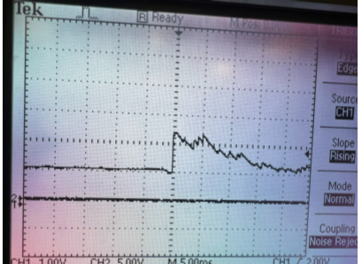
Firstly a clap or snap would be created then travel through the air into the microphone
placed in the x-y plan of our workstation. These waves would be converted to a waveform that had a clean rising edge
which was used as a way to detect if a microphone picked up a sound. From here we found out the order of which the
microphone picked up the sound first, second, then third by time of flight and combined the first and second
microphones into detection pairs. With these pairs we could creat an angle of where the sound came from relative to
the center of our setup allowing us to ping on a VGA screen where the sound came from.
High Level Design
Rationale and Sources of Your Project Idea
Our project's original inspiration was a turret that would be able track someone based on their distance, and then
track them.
However, we settled on the design of an audio tracker and was able to pinpoint the location of any sound made near
the microphones.
While we came up with the idea on our own we did find a demo that Professor Van Adams did with an ultrasonic
rangefinder, in which we found the mechanical part for controlling
the angle and tilt of the turret.
In addition we found another group towards the end of our project which we ended up incorporating their algorithm
for locating distance from the sound into our final project.
Background Math
What we did was assume that the first two microphones were parallel as another group from 2013 did.
From this assumption we were able to make a right angle between the microphones and the sound, which would allow us
to get the hypotenuse, the distance between the two microphones
and the time it takes to travel, and the opposite, the distance measured allowing us to get the angle by the inverse
sin
Program/Hardware Design
Program Details
PWM ISR
The first ISR we have is the PWM ISR, which repeats every time the PWM wraps. The first thing we do is clear the
interrupt flag that brought us to the wrap.
In the ISR we first have to figure out which two microphones heard the sound first and second.
For this, we take the value of cycle after, which is the cycle after the first one heard it.
So we take the minimum of the three values for the first value, and then we take the minimum of the other two as the
second one.
First, we calculate the angle based on the arcsin(cycle*speed if sound/ microphone distance) in which we found that
the ratio of speed of sound to our microphone distance was roughly
3/800. Then depending on which two we think it is parallel to, the first two microphones heard we calculated the
angle based on that assumption.
If it heard microphone one and zero we would say the angle was parallel to pi/3. And added it to pi/3 it if
microphone one heard it first and subtracted it from pi/3 if
microphone zero heard it first. If the angle is different then we configured it to sweep in either the positive or
negative direction.
If it sweeps it goes to 2000 the first round, then 6500 next pass, 4000 the last pass, which will sweep the left
side.
And if it is positive we set sweep - 1 and then pass to 12000,
then 6500 on the next pass, then 10000 on the final pass. Then we update the pwm line of the turn PWM channel.
Finally, we signal the vga semaphore so the vga can draw.
GPIO thread
The next thread is our GPIO thread. We made sure that the thread was always running and the only only thread
running where we are continuously polling, each of the three microphones.
First we start the thread then go into an infinite while loop as we want it continuously polling.
In this while loop we set the the booleans for wether we got a reading from the adc connected to gpio 26, 27 and 28
together and set that boolean to false,
and reinitialize the cycle to 0. Howe the adc round robin work works is that it takes the bit and if the bit is high
it takes that input and adds it into the round robin cycle,
if the first bit is for gpio 26, the second bit is for gpio 27, third bit is for gpio 28, and fourth bit is the gpio
29(the temperature sensor),
white the first bit is the leftmost bit. Then we set the adc round robin mode to 7(0111) so that we are round robin
polling from the correct gpio pins.
Next we are ready to enter our polling while loop. Then we read from the adc and compare it to the correct value
store it in the correct gp variable and increment the cycle.
It polls this loop until one of the gp variables become true.
After we exit this we sit the first cycle to the current cycle, and the last cycle to the current cyle added to the
cycle limit.
This is the cycle which deem the sound as just not picked up by one of the microphones and sets it to one after the
last cycle to indicate that the microphone
didn't pick up a sound but still can use it in calculations if necessary.
Next we check which ones were picked up and poll the rest accordingly and record the cycle that they were detected
in cycle detected, where gpio 26 is stored in the 0th
spot in the array gpio 27 is stored in the 1rst spot in the arry and gpio 28 is stored in the 2nd spot in the array.
Also when they are all detected(where it hears the sound before the Cycle limit is reached) then we toggle the led,
we toggle the
LED(by setting the gpio_put to negated boolean value of gpio_get) connected to gpio 15 if gpio 26 is detected, 14 if
27 is detected and 13 if 28 is detected.
If they are all detected then we then we set all of the cycle detected to the current cycle, then we toggle the LED,
where we toggle the led. If 2 of the gpios are
detected then we first set the cycle_detected for the two that were detected and toggle their respective gpio pins.
Then we set the respective adc
round robin setting so that only the one that we didn't pick up yet is high(1 for 26, 2 for 27, 4 for 28) and then
continuously poll for that one.
And then if it either detects it or if the cycle is greater than the last cycle(timeout) we end record the
respective cycle in the correct spot in the cycle_detected array
and move on to the next part. If the current cycle is greater than the current cycle then we don't toggle the
respective LED, otherwise we do.
The last scenario where we only detect one. For that we would first store the correct cyle in the cycle_detected
array and toggle the respective gpio.
Then we set the round robin to the correct value(6 for 27 and 28 undetected, 5 for 26 and 28 undetected and 3 for 26
and 27 undecided) then we continue polling the two
gpios breaking out of the polling while loop if the adc reading from either gpio breaches the threshold or the cycle
exceeds the lastcycle which we break out of the while loop.
If both are detected in the same cycle then we toggle then we have the cycle_detected and toggle the respective gpio
pins. If the cycle is greater than cycle detected(timed out)
then we set both cycle detected but don’t toggle the gpio pins. If only one is detected then we update the cycle
detected for that respective pin and toggle that gpio then we poll
for the last one like we did before. Now that all of the gpio have a cycle associated with them (either because they
timed out or detected something)
we regularize our data by creating an array with the difference in first cycle detected and the rest. We first loop
over all the values and record the minimum value,
then we update the cycle_after array 0 is associated with gpio 26, 1 with 27 and 2 with 28
(cycle_after[x]=cycle_detected[x]-min_value).
VGA Thread
The next thread that is running is the VGA protothread. We start off by initializing the semicircle by drawing a
circle and the crosshair lines and the label of the graph
and then filling in the right half of the circle using the fillrect, drawH, drawV and drawCircle functions in the
VGA.c file.
Next we wait on the binary semaphore so our value is limited by pwm wrap. First we throttle the VGA so that we can
rate limit it so that it doesn't change too fast.
Next we erase the current point by filling in the inner circle of the semi circle with black (a black circle with a
radius one less than the outer circle with the same center).
Next we redraw the lines for the vertical and horizontal lines of the semicircle.
Next we calculate the x and y coordinates and store them in the xCoord and yCoord variables, we use the law where
cos(angle) *100 and then add it
to the x coordinate of the center of the circle.
And cos(angle) *100 and add it to the y coordinate of the center of the circle.
Serial thread
We did have a serial thread that was mainly used for debugging. We chose to make all reads and writes non blocking
as it wasn't essential for our design and we didn't want
it using the cpu unless we needed to read or write something for debugging.
In this thread we printed out the microphone readings and the angle and the cycle detected to the screen, and took
input that would allow us to change certain variables for testing.
If it took in an i it would change the tiltControl, u would change the turnControl pwm channel, and s would change
the sweep value.
Code setup
For the setup we first initialize the VGA thread and overclock the system clock to 25000 kHz, so that we have more
cycles for calculations.
This does affect the actual values for the PWM duty cycle to get the same duty cycle on the normally clocked
cpus(the
Sound Bite:
Our project was a soundar, that allowed us to pinpoint any sound that was heard in
front of the machine.
Summary:
Firstly a clap or snap would be created then travel through the air into the microphone
placed in the x-y plan of our workstation. These waves would be converted to a waveform that had a clean rising edge
which was used as a way to detect if a microphone picked up a sound. From here we found out the order of which the
microphone picked up the sound first, second, then third by time of flight and combined the first and second
microphones into detection pairs. With these pairs we could creat an angle of where the sound came from relative to
the center of our setup allowing us to ping on a VGA screen where the sound came from.
High Level Design
Rationale and Sources of Your Project Idea
Our project's original inspiration was a turret that would be able track someone based on their distance, and then
track them.
However, we settled on the design of an audio tracker and was able to pinpoint the location of any sound made near
the microphones.
While we came up with the idea on our own we did find a demo that Professor Van Adams did with an ultrasonic
rangefinder, in which we found the mechanical part for controlling
the angle and tilt of the turret.
In addition we found another group towards the end of our project which we ended up incorporating their algorithm
for locating distance from the sound into our final project.
Background Math
What we did was assume that the first two microphones were parallel as another group from 2013 did.
From this assumption we were able to make a right angle between the microphones and the sound, which would allow us
to get the hypotenuse, the distance between the two microphones
and the time it takes to travel, and the opposite, the distance measured allowing us to get the angle by the inverse
sin
Program/Hardware Design
Program Details
PWM ISR
The first ISR we have is the PWM ISR, which repeats every time the PWM wraps. The first thing we do is clear the
interrupt flag that brought us to the wrap.
In the ISR we first have to figure out which two microphones heard the sound first and second.
For this, we take the value of cycle after, which is the cycle after the first one heard it.
So we take the minimum of the three values for the first value, and then we take the minimum of the other two as the
second one.
First, we calculate the angle based on the arcsin(cycle*speed if sound/ microphone distance) in which we found that
the ratio of speed of sound to our microphone distance was roughly
3/800. Then depending on which two we think it is parallel to, the first two microphones heard we calculated the
angle based on that assumption.
If it heard microphone one and zero we would say the angle was parallel to pi/3. And added it to pi/3 it if
microphone one heard it first and subtracted it from pi/3 if
microphone zero heard it first. If the angle is different then we configured it to sweep in either the positive or
negative direction.
If it sweeps it goes to 2000 the first round, then 6500 next pass, 4000 the last pass, which will sweep the left
side.
And if it is positive we set sweep - 1 and then pass to 12000,
then 6500 on the next pass, then 10000 on the final pass. Then we update the pwm line of the turn PWM channel.
Finally, we signal the vga semaphore so the vga can draw.
GPIO thread
The next thread is our GPIO thread. We made sure that the thread was always running and the only only thread
running where we are continuously polling, each of the three microphones.
First we start the thread then go into an infinite while loop as we want it continuously polling.
In this while loop we set the the booleans for wether we got a reading from the adc connected to gpio 26, 27 and 28
together and set that boolean to false,
and reinitialize the cycle to 0. Howe the adc round robin work works is that it takes the bit and if the bit is high
it takes that input and adds it into the round robin cycle,
if the first bit is for gpio 26, the second bit is for gpio 27, third bit is for gpio 28, and fourth bit is the gpio
29(the temperature sensor),
white the first bit is the leftmost bit. Then we set the adc round robin mode to 7(0111) so that we are round robin
polling from the correct gpio pins.
Next we are ready to enter our polling while loop. Then we read from the adc and compare it to the correct value
store it in the correct gp variable and increment the cycle.
It polls this loop until one of the gp variables become true.
After we exit this we sit the first cycle to the current cycle, and the last cycle to the current cyle added to the
cycle limit.
This is the cycle which deem the sound as just not picked up by one of the microphones and sets it to one after the
last cycle to indicate that the microphone
didn't pick up a sound but still can use it in calculations if necessary.
Next we check which ones were picked up and poll the rest accordingly and record the cycle that they were detected
in cycle detected, where gpio 26 is stored in the 0th
spot in the array gpio 27 is stored in the 1rst spot in the arry and gpio 28 is stored in the 2nd spot in the array.
Also when they are all detected(where it hears the sound before the Cycle limit is reached) then we toggle the led,
we toggle the
LED(by setting the gpio_put to negated boolean value of gpio_get) connected to gpio 15 if gpio 26 is detected, 14 if
27 is detected and 13 if 28 is detected.
If they are all detected then we then we set all of the cycle detected to the current cycle, then we toggle the LED,
where we toggle the led. If 2 of the gpios are
detected then we first set the cycle_detected for the two that were detected and toggle their respective gpio pins.
Then we set the respective adc
round robin setting so that only the one that we didn't pick up yet is high(1 for 26, 2 for 27, 4 for 28) and then
continuously poll for that one.
And then if it either detects it or if the cycle is greater than the last cycle(timeout) we end record the
respective cycle in the correct spot in the cycle_detected array
and move on to the next part. If the current cycle is greater than the current cycle then we don't toggle the
respective LED, otherwise we do.
The last scenario where we only detect one. For that we would first store the correct cyle in the cycle_detected
array and toggle the respective gpio.
Then we set the round robin to the correct value(6 for 27 and 28 undetected, 5 for 26 and 28 undetected and 3 for 26
and 27 undecided) then we continue polling the two
gpios breaking out of the polling while loop if the adc reading from either gpio breaches the threshold or the cycle
exceeds the lastcycle which we break out of the while loop.
If both are detected in the same cycle then we toggle then we have the cycle_detected and toggle the respective gpio
pins. If the cycle is greater than cycle detected(timed out)
then we set both cycle detected but don’t toggle the gpio pins. If only one is detected then we update the cycle
detected for that respective pin and toggle that gpio then we poll
for the last one like we did before. Now that all of the gpio have a cycle associated with them (either because they
timed out or detected something)
we regularize our data by creating an array with the difference in first cycle detected and the rest. We first loop
over all the values and record the minimum value,
then we update the cycle_after array 0 is associated with gpio 26, 1 with 27 and 2 with 28
(cycle_after[x]=cycle_detected[x]-min_value).
VGA Thread
The next thread that is running is the VGA protothread. We start off by initializing the semicircle by drawing a
circle and the crosshair lines and the label of the graph
and then filling in the right half of the circle using the fillrect, drawH, drawV and drawCircle functions in the
VGA.c file.
Next we wait on the binary semaphore so our value is limited by pwm wrap. First we throttle the VGA so that we can
rate limit it so that it doesn't change too fast.
Next we erase the current point by filling in the inner circle of the semi circle with black (a black circle with a
radius one less than the outer circle with the same center).
Next we redraw the lines for the vertical and horizontal lines of the semicircle.
Next we calculate the x and y coordinates and store them in the xCoord and yCoord variables, we use the law where
cos(angle) *100 and then add it
to the x coordinate of the center of the circle.
And cos(angle) *100 and add it to the y coordinate of the center of the circle.
Serial thread
We did have a serial thread that was mainly used for debugging. We chose to make all reads and writes non blocking
as it wasn't essential for our design and we didn't want
it using the cpu unless we needed to read or write something for debugging.
In this thread we printed out the microphone readings and the angle and the cycle detected to the screen, and took
input that would allow us to change certain variables for testing.
If it took in an i it would change the tiltControl, u would change the turnControl pwm channel, and s would change
the sweep value.
Code setup
For the setup we first initialize the VGA thread and overclock the system clock to 25000 kHz, so that we have more
cycles for calculations.
This does affect the actual values for the PWM duty cycle to get the same duty cycle on the normally clocked
cpus(the
Technologies used
Hardware components
- IMU
- microphone
- ADC
Software & tools
- C
- Arduino IDE
Project demo video
What you get
- Working project / hardware kit, tested before delivery
- Complete source code with explanation
- Project demo and guidance for your viva
- Project report, PPT and IEEE paper support (on request)
Delivery & Payment
Delivery takes a minimum of two weeks from the date your inquiry is confirmed.
Payment is in two parts:
• 50% advance to start the project
• Remaining 50% before delivery
Note:
• Documentation and PPT are not included by default
• If you need documentation/PPT, it can be arranged for extra time and cost
We'll confirm the exact timeline and cost with you after reviewing your requirements.
Related Embedded Systems projects

Embedded Systems
Gas Leakage Detector Using Arduino
A budget-friendly LPG gas leak detector built with an Arduino and MQ-5 gas sensor, triggering a buzzer and LED when unsafe gas levels are de...
View project
Embedded Systems
Simple Alarm System
A beginner-friendly home alarm with PIR motion sensing, keypad PIN entry, and separate entry/exit timing delays, built to be easy to expand.
View project
Embedded Systems
Ultrasonic Sensor Project with Arduino UNO Q
A beginner-friendly first Arduino UNO Q project: a servo-swept ultrasonic sensor that renders a live sweeping radar display in a web browser...
View project
Embedded Systems
3D Audio Localization
[Fall 2025] We designed a real-time embedded system that localizes sound sources in three dimensions and visualizes them live using a four-m...
View project