Air Drums Fall 2023
[Fall 2023] - Sound Bite: Experience the future of drumming with our innovative air drum kit—no noise, all rhythm.
- Suitable forB.Tech/B.E Embedded Systems students
- Build time4-6 weeks
- LevelBeginner
- Available atAjvika Labs, Kakinada
About this project
Toggle navigation
Air Drums
Project Introduction
High Level Design
Design Details
Results
Conclusions
Appendix
ECE 5730 Final Project: Air Drums
Demonstration Video
Project Introduction
- Sound Bite: Experience the future of drumming with our innovative air drum kit—no noise, all rhythm.
We've developed an electronic drum kit with an interface consisting of two drumsticks, each equipped with an Inertial Measurement Unit sensor and a toggle button, along with a kick pedal. The traditional drum pads or any striking surface are omitted. When a drumstick downstroke or a press of the pedal is detected, drum sounds purely synthesized by the Raspberry Pi Pico will be played, accompanied by a synchronized visual effect on the VGA screen. The drum kit features three types of sounds—hi-hat, snare, and bass—where the toggle buttons on the drumsticks allow for seamless switching between the hi-hat and the snare sounds. Now you can drum in the air—no more noise from striking the pads, and you can plug in headphones to completely avoid disturbing others. Plus, it looks pretty cool!
High Level Design
1. Overview
Our original plan when brainstorming project ideas was to synthesize various drum sounds and play them through keypad button press. As this idea was too simple, we debated connecting a predefined interface, such as a guitar hero drum kit, to the RP2040 and emulating a real drum playing experience. However, after some research, we discovered that resources involving the operation and wiring of the drum pads were limited. Instead, we decided to develop our own interface, in the form of “Air drum sticks”, in order to emulate a drum-kit playing experience, without the need of physical drum pads. This idea was inspired by a previous Microncontrollers project that can be found
here
, where an air drum kit was also created. Their “Air Drum” interface was created using IR sensors while ours was made using the MPU6050 Inertial Measurement Unit (IMU). Similar to this group, we produced drum sounds based on the Karplus-Strong algorithm.
2. Background Math:
Karplus-Strong Algorithm
[1]
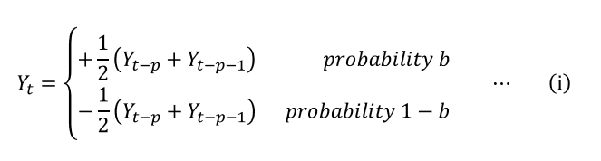
The equation (i) shows the probabilistic recurrence relation pattern for computing the value (Y_t) of a sample point for the drum sound. First of all, the buffer (which can also be regarded as a wavetable) needs to be initialized. It can be filled either with varying values according to the desired sound to be produced or entirely with a constant, as the following drum algorithm will introduce randomness. For the value at moment t, two values, which are p and p+1 indices ahead respectively, are read from the wavetable and averaged, and the polarity of this result is determined by a random-bit generator.
The parameter b here is called the blend factor. If its value is 1, then Y_t will only be equal to the positive average, producing a plucked string sound; when b is set to around ½, the sound becomes aperiodic and randomized, appearing to be drum-like. The computed value is then updated into the wavetable where it will be indexed in the next cycle.
Figure 1 illustrates the process described above. The average acts as a filter that suppresses the high frequency components more than the low frequency components, emulating the vibration of a physical drum head.
Figure 1: The Drum Algorithm Block Diagram
The parameter p stands for pitch factor, and the value of it also represents the total length of the wavetable. In theory, when the blend factor is set to around ½, as the sound becomes aperiodic, the value of p should be able to control the decay time of the noise burst, and we should be able to generate different drum sounds by changing this value, for example, larger number for a snare and smaller number for toms.
3. Logical Structure
There are three essential elements of our designed, outlined in the following block diagram:
Figure 2: Block diagram visualizing the three essential elements of our project
Figure 2 shows that there are three essential aspects to the functionality of our project. The RP2040 will be responsible for hosting the drum stick interface, producing the sounds that will be heard and outputting visual effects onto the VGA screen to enhance our design.
The methods by which we develop these three elements is shown below:
Figure 3: Block diagram visualizing the hardware connections of our project
Stick movement will be tracked via the two MPU6050 IMUs. When a downward stroke is detected, the RP2040 should send the selected synthesized audio signal of a drum sound to the DAC output which will be played through the speakers.
4. Hardware/software trade-offs
a. DAC & Speaker Output:
For sound output a single DAC was used to output all three drum sounds. The DAC was connected to a single audio jack. Both sticks output independently through both channels of the DAC and the DAC outputs A and B were both connected to the audio jack output. The kick drum shared the DAC channel output of the left stick. This was done in order to conserve resources and board space. If we were to add another DAC for the kick drum, we would also need another audio jack, and therefore another set of speakers. The kick drum shares the audio output of the left stick which is often playing the snare drum for right-handed drummers. As typically drum patterns do not usually feature the snare drum and the kick drum playing at the same time, we believe this is a good tradeoff. This will be discussed further in future sections.
b. Two Separate I2C channels Used with Similarly Addressed IMUs:
We noticed that the IMUs would typically glitch when connected to the same I2C channel despite using different addresses. This may be due to a loose connection on our A0 pin (which controls the address that the IMU uses). Due to this, we decided to use two complete separate I2C channels on the RP2040. This allowed for stick functionality to work flawlessly. The downside of this is the use of a second I2C channel, however, as the IMUs are the only I2C modules used in this project, this was perfectly fine.
c. Storing Waveforms in Memory vs. Producing Live:
Drum sounds will be played in the future using an interrupt service routine, called 40000 times a second (40khz). We spent a significant amount of time trying to enhance the quality of the drum sounds that were produced, making them as realistic and similar to actual kick, hi-hat and snare-drum sounds as possible. Due to this, we did not produce a massive amount of sounds. Therefore, we decided to store the sound wave values in arrays in memory, and had the ISR play through the arrays of the sound that was requested upon each downstroke. This ensured that our sounds would be played within the duration of the ISR, and minimized the number of computations required in the sound producing interrupt service routine.
d. Use of ISRs for sound playing instead of DMAs:
When experimenting with DMA channels, we noticed that our drum sounds were often warped and cut-off before their duration was complete. Moreover, since we chose to synthesize the sound waveforms and store them in the memory beforehand, if we use the DMA channel to carry the values directly to the DAC for output, it would be necessary to create corresponding DAC output format data arrays for each sound waveform. Unlike using ISR, where only one value at a time is taken from the waveform array and processed, this double matrix approach significantly increases memory consumption. As our system will not be used for anything else besides stick detection and sound production, we decided that using an ISR to play the sounds would not only be easier but also produce better quality sounds.
5. Relevant existing patents, copyrights, and trademarks
This patent
is related to our project, but a crucial distinction lies in the fact that our system doesn't require triggering pads. Instead, our “air drums” relies on IMU sensors for detecting drumstick movement to determine when to trigger the sound.
Design Details
Figure 4: Hardware setup
IMU SETUP:
- GPIO 0 ---> MPU6050 SDA i2c0
- GPIO 1 ---> MPU6050 SCL i2c0
- GPIO 26 ---> MPU6050 SDA i2c1
- GPIO 27 ---> MPU6050 SCL i2c1
- 3.3V ---> MPU6050 VCC
- RP2040 GND ---> MPU6050 GND
PUSH BUTTONS:
- GPIO 2 ---> 330 ohms ---> BUTTON 0 ---> 3.3V
- GPIO 3 ---> 330 ohms ---> BUTTON 1 ---> 3.3V
DAC CONNECTIONS:
- GPIO 5 ---> CS
- GPIO 6 ---> CLK
- GPIO 7 ---> Transmit
- GPIO 8 ---> Receive
VGA CONNECTIONS:
- GPIO 16 ---> VGA Hsync
- GPIO 17 ---> VGA Vsync
- GPIO 18 ---> 330 ohm resistor ---> VGA Red
- GPIO 19 ---> 330 ohm resistor ---> VGA Green
- GPIO 20 ---> 330 ohm resistor ---> VGA Blue
- RP2040 GND ---> VGA GND
Figure 5: OP-AMP IC Chip utilized to create comparator circuit
KICK PEDAL & COMPARATOR:
- GPIO 28 ---> 330 ohms ---> MCP6242 VOUTA
- PEDAL ---> MCP6242 VINA+
- 0.5V ---> MCP6242 VINA-
- 3.3V ---> MCP6242 VDD
- RP2040 GND ---> MCP6242 VSS
1. Audio Synthesis and Output
a. Software
Our sound synthesis method is based on the principles of the Karplus-Strong algorithm, but with changes and modifications in implementation. The most significant difference is that, instead of computing the sound in real-time, we chose to complete the synthesis in the main code at the program's startup and store the sound waveforms in memory, which is then accessed by an interrupt service routine. To achieve this, in addition to the original Karplus-Strong algorithm (refer to equation (i) and Figure X), each time a value is computed, besides updating the value at the end of the buffer, it is also simultaneously stored in the synthesized drum sound waveform array. In this way, we ensured the consistency of the drum set sounds, and we have achieved realistic sound effects through parameter adjustments.
Apart from the necessary initializations and variable declarations, the code for the audio synthesis and output part is primarily divided into the following modules: the Karplus-Strong algorithm function u
Air Drums
Project Introduction
High Level Design
Design Details
Results
Conclusions
Appendix
ECE 5730 Final Project: Air Drums
Demonstration Video
Project Introduction
- Sound Bite: Experience the future of drumming with our innovative air drum kit—no noise, all rhythm.
We've developed an electronic drum kit with an interface consisting of two drumsticks, each equipped with an Inertial Measurement Unit sensor and a toggle button, along with a kick pedal. The traditional drum pads or any striking surface are omitted. When a drumstick downstroke or a press of the pedal is detected, drum sounds purely synthesized by the Raspberry Pi Pico will be played, accompanied by a synchronized visual effect on the VGA screen. The drum kit features three types of sounds—hi-hat, snare, and bass—where the toggle buttons on the drumsticks allow for seamless switching between the hi-hat and the snare sounds. Now you can drum in the air—no more noise from striking the pads, and you can plug in headphones to completely avoid disturbing others. Plus, it looks pretty cool!
High Level Design
1. Overview
Our original plan when brainstorming project ideas was to synthesize various drum sounds and play them through keypad button press. As this idea was too simple, we debated connecting a predefined interface, such as a guitar hero drum kit, to the RP2040 and emulating a real drum playing experience. However, after some research, we discovered that resources involving the operation and wiring of the drum pads were limited. Instead, we decided to develop our own interface, in the form of “Air drum sticks”, in order to emulate a drum-kit playing experience, without the need of physical drum pads. This idea was inspired by a previous Microncontrollers project that can be found
here
, where an air drum kit was also created. Their “Air Drum” interface was created using IR sensors while ours was made using the MPU6050 Inertial Measurement Unit (IMU). Similar to this group, we produced drum sounds based on the Karplus-Strong algorithm.
2. Background Math:
Karplus-Strong Algorithm
[1]
The equation (i) shows the probabilistic recurrence relation pattern for computing the value (Y_t) of a sample point for the drum sound. First of all, the buffer (which can also be regarded as a wavetable) needs to be initialized. It can be filled either with varying values according to the desired sound to be produced or entirely with a constant, as the following drum algorithm will introduce randomness. For the value at moment t, two values, which are p and p+1 indices ahead respectively, are read from the wavetable and averaged, and the polarity of this result is determined by a random-bit generator.
The parameter b here is called the blend factor. If its value is 1, then Y_t will only be equal to the positive average, producing a plucked string sound; when b is set to around ½, the sound becomes aperiodic and randomized, appearing to be drum-like. The computed value is then updated into the wavetable where it will be indexed in the next cycle.
Figure 1 illustrates the process described above. The average acts as a filter that suppresses the high frequency components more than the low frequency components, emulating the vibration of a physical drum head.
Figure 1: The Drum Algorithm Block Diagram
The parameter p stands for pitch factor, and the value of it also represents the total length of the wavetable. In theory, when the blend factor is set to around ½, as the sound becomes aperiodic, the value of p should be able to control the decay time of the noise burst, and we should be able to generate different drum sounds by changing this value, for example, larger number for a snare and smaller number for toms.
3. Logical Structure
There are three essential elements of our designed, outlined in the following block diagram:
Figure 2: Block diagram visualizing the three essential elements of our project
Figure 2 shows that there are three essential aspects to the functionality of our project. The RP2040 will be responsible for hosting the drum stick interface, producing the sounds that will be heard and outputting visual effects onto the VGA screen to enhance our design.
The methods by which we develop these three elements is shown below:
Figure 3: Block diagram visualizing the hardware connections of our project
Stick movement will be tracked via the two MPU6050 IMUs. When a downward stroke is detected, the RP2040 should send the selected synthesized audio signal of a drum sound to the DAC output which will be played through the speakers.
4. Hardware/software trade-offs
a. DAC & Speaker Output:
For sound output a single DAC was used to output all three drum sounds. The DAC was connected to a single audio jack. Both sticks output independently through both channels of the DAC and the DAC outputs A and B were both connected to the audio jack output. The kick drum shared the DAC channel output of the left stick. This was done in order to conserve resources and board space. If we were to add another DAC for the kick drum, we would also need another audio jack, and therefore another set of speakers. The kick drum shares the audio output of the left stick which is often playing the snare drum for right-handed drummers. As typically drum patterns do not usually feature the snare drum and the kick drum playing at the same time, we believe this is a good tradeoff. This will be discussed further in future sections.
b. Two Separate I2C channels Used with Similarly Addressed IMUs:
We noticed that the IMUs would typically glitch when connected to the same I2C channel despite using different addresses. This may be due to a loose connection on our A0 pin (which controls the address that the IMU uses). Due to this, we decided to use two complete separate I2C channels on the RP2040. This allowed for stick functionality to work flawlessly. The downside of this is the use of a second I2C channel, however, as the IMUs are the only I2C modules used in this project, this was perfectly fine.
c. Storing Waveforms in Memory vs. Producing Live:
Drum sounds will be played in the future using an interrupt service routine, called 40000 times a second (40khz). We spent a significant amount of time trying to enhance the quality of the drum sounds that were produced, making them as realistic and similar to actual kick, hi-hat and snare-drum sounds as possible. Due to this, we did not produce a massive amount of sounds. Therefore, we decided to store the sound wave values in arrays in memory, and had the ISR play through the arrays of the sound that was requested upon each downstroke. This ensured that our sounds would be played within the duration of the ISR, and minimized the number of computations required in the sound producing interrupt service routine.
d. Use of ISRs for sound playing instead of DMAs:
When experimenting with DMA channels, we noticed that our drum sounds were often warped and cut-off before their duration was complete. Moreover, since we chose to synthesize the sound waveforms and store them in the memory beforehand, if we use the DMA channel to carry the values directly to the DAC for output, it would be necessary to create corresponding DAC output format data arrays for each sound waveform. Unlike using ISR, where only one value at a time is taken from the waveform array and processed, this double matrix approach significantly increases memory consumption. As our system will not be used for anything else besides stick detection and sound production, we decided that using an ISR to play the sounds would not only be easier but also produce better quality sounds.
5. Relevant existing patents, copyrights, and trademarks
This patent
is related to our project, but a crucial distinction lies in the fact that our system doesn't require triggering pads. Instead, our “air drums” relies on IMU sensors for detecting drumstick movement to determine when to trigger the sound.
Design Details
Figure 4: Hardware setup
IMU SETUP:
- GPIO 0 ---> MPU6050 SDA i2c0
- GPIO 1 ---> MPU6050 SCL i2c0
- GPIO 26 ---> MPU6050 SDA i2c1
- GPIO 27 ---> MPU6050 SCL i2c1
- 3.3V ---> MPU6050 VCC
- RP2040 GND ---> MPU6050 GND
PUSH BUTTONS:
- GPIO 2 ---> 330 ohms ---> BUTTON 0 ---> 3.3V
- GPIO 3 ---> 330 ohms ---> BUTTON 1 ---> 3.3V
DAC CONNECTIONS:
- GPIO 5 ---> CS
- GPIO 6 ---> CLK
- GPIO 7 ---> Transmit
- GPIO 8 ---> Receive
VGA CONNECTIONS:
- GPIO 16 ---> VGA Hsync
- GPIO 17 ---> VGA Vsync
- GPIO 18 ---> 330 ohm resistor ---> VGA Red
- GPIO 19 ---> 330 ohm resistor ---> VGA Green
- GPIO 20 ---> 330 ohm resistor ---> VGA Blue
- RP2040 GND ---> VGA GND
Figure 5: OP-AMP IC Chip utilized to create comparator circuit
KICK PEDAL & COMPARATOR:
- GPIO 28 ---> 330 ohms ---> MCP6242 VOUTA
- PEDAL ---> MCP6242 VINA+
- 0.5V ---> MCP6242 VINA-
- 3.3V ---> MCP6242 VDD
- RP2040 GND ---> MCP6242 VSS
1. Audio Synthesis and Output
a. Software
Our sound synthesis method is based on the principles of the Karplus-Strong algorithm, but with changes and modifications in implementation. The most significant difference is that, instead of computing the sound in real-time, we chose to complete the synthesis in the main code at the program's startup and store the sound waveforms in memory, which is then accessed by an interrupt service routine. To achieve this, in addition to the original Karplus-Strong algorithm (refer to equation (i) and Figure X), each time a value is computed, besides updating the value at the end of the buffer, it is also simultaneously stored in the synthesized drum sound waveform array. In this way, we ensured the consistency of the drum set sounds, and we have achieved realistic sound effects through parameter adjustments.
Apart from the necessary initializations and variable declarations, the code for the audio synthesis and output part is primarily divided into the following modules: the Karplus-Strong algorithm function u
Technologies used
Hardware components
- RP2040
- Raspberry Pi Pico
- IMU
- MPU6050
- IR sensor
- speaker
- DAC
Software & tools
- C
- Arduino IDE
Project demo video
What you get
- Working project / hardware kit, tested before delivery
- Complete source code with explanation
- Project demo and guidance for your viva
- Project report, PPT and IEEE paper support (on request)
Delivery & Payment
Delivery takes a minimum of two weeks from the date your inquiry is confirmed.
Payment is in two parts:
• 50% advance to start the project
• Remaining 50% before delivery
Note:
• Documentation and PPT are not included by default
• If you need documentation/PPT, it can be arranged for extra time and cost
We'll confirm the exact timeline and cost with you after reviewing your requirements.
Related Embedded Systems projects

Embedded Systems
Gas Leakage Detector Using Arduino
A budget-friendly LPG gas leak detector built with an Arduino and MQ-5 gas sensor, triggering a buzzer and LED when unsafe gas levels are de...
View project
Embedded Systems
Simple Alarm System
A beginner-friendly home alarm with PIR motion sensing, keypad PIN entry, and separate entry/exit timing delays, built to be easy to expand.
View project
Embedded Systems
Ultrasonic Sensor Project with Arduino UNO Q
A beginner-friendly first Arduino UNO Q project: a servo-swept ultrasonic sensor that renders a live sweeping radar display in a web browser...
View project
Embedded Systems
3D Audio Localization
[Fall 2025] We designed a real-time embedded system that localizes sound sources in three dimensions and visualizes them live using a four-m...
View project