
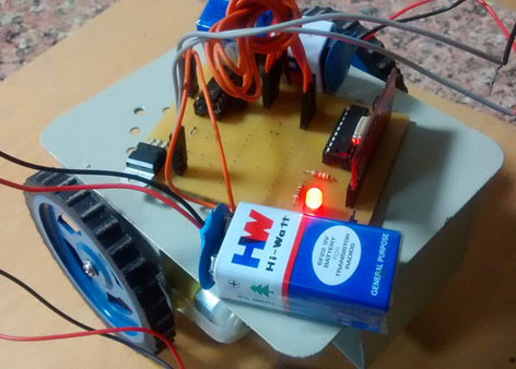
RF Controlled Robot
In this tutorial we are going to design a very interesting robot, that is RF controlled Robot. Interesting thing in this project is that it will run without using any microcontroller. Here we will run it directly by RF Decoder and Motor Driver.
- Suitable forB.Tech ECE students
- Build time5-7 weeks
- LevelAdvanced
- Available atAjvika Labs, Kakinada
About this project
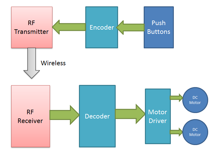
RF controlled robot is controlled by using Four push button placed at transmitter side. Here we only need to push the buttons to control the robot. A transmitting device is used in your hand which also contains a RF Transmitter and a RF Encoder. This transmitter part will transmit command to robot so that it can do the required task like moving forward, reverse, turning left, turning right and stop. All these tasks will perform by using four push buttons that are placed on RF transmitter.
Motor Driver L293D - 1
Battery Connector - 3
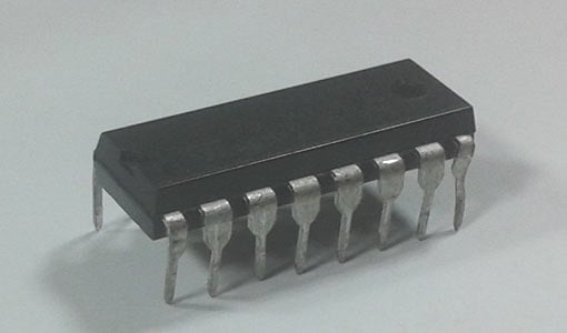
L293D is a motor driver IC which has two channels for driving two motors. L293D has Two inbuilt Transistor Darlington pair for current amplification and an separate power supply pin for giving external supply for motors.
RF Transmitter and Receiver
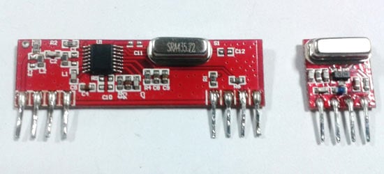
This is a ASK Hybrid Transmitter and receiver module operates at 433Mhz frequency. This module has a crystal stabilized oscillator for maintain accurate frequency control for best range. There we have to need only one antenna externally for this module.
RF Transmitter Features:
Frequency Range: 433 Mhz
Output Power: 4-16dBm
Input supply: 3 to 12 volt dc
RF Receiver Features:
Sensitivity: -105dBm
Low Power Consumption
Supply voltage: 5 volt
This Module is very cost efficient where long range RF communication is required. This module does not send data using UART communication of PC or microcontroller directly because there is lots of noise at this frequency and its Analog technology. We can use this module with the help of encoder and decoder ICs which extract data from the noise.
The range of transmitter is about 100 meters at maximum supply voltage and for 5 volt the range of transmitter is about 50-60 meter with using a simple wire of single code 17cm length antenna.
Pin Description of RF Tx
Data In - This pin accept serial data from encoder
Vcc - +5 Volt should be connect to this pin
Antenna - A wrapped connect to this pin for proper transmission of data
Pin Description of RF Rx
Data In - This pin give output serial data to Decoder
Data In - This pin give output serial data to Decoder
Vcc - +5 Volt should be connect to this pin
Vcc - +5 Volt should be connect to this pin
Antenna - A wrapped connect to this pin for proper Reception of data
Circuit Diagrams and Explanation
Circuit Diagram for RF Transmitter:
Circuit Diagram for RF Receiver:
As shown in above figures, circuit diagrams for RF controlled robot are quite simple where a RF pair is used for communication. Connections for transmitter and receiver show in circuit diagrams. Two 9 volt batteries are used to power the motor driver and remaining Rx Circuit. And another 9 Volt battery is used to power the transmitter.
RF Controlled Robot has two main parts namely:
[Also check: RF Transmitter and Receiver Circuit ]
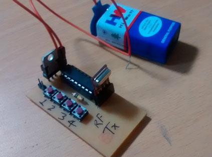
In transmitter part a data Encoder and a RF transmitter is used. As we have already mentioned above that we are using four push buttons to run the robot, these four buttons are connected with Encoder with respect to ground. When we will press any button encoder will get a digital LOW signal and then applied this signal serially to RF transmitter. The Encoder IC HT12E encodes data or signal or converting it into serial form and then sends this signal by using RF transmitter into the environment.
At the receiver end we have used RF receiver to receive data or signal and then applied to HT12D decoder. This decoder IC converts the received serial data to parallel and then send these decoded signal to L293D Motor driver IC. According to the received data robot runs by using two dc motor in forward, reverse, left, right and stop direction.
Working of RF Controlled Robot:
RF controlled robot move according to button pressed at Transmitter.
Button Pressed at Transmitter
Moving Direction of Robot
First and Second (1 & 2)
Third and Fourth (3 & 4)
When we press first button (1 mention on circuit and hardware) robot start to moving left side and moving continues until the button is released.
When we press second button at transmitter, robot start moving in right side until button is released.
When we press first and second button at the same time, Robot start moving in forward direction until push buttons are released.
When we press third and fourth button at the same time, robot start moving in backward direction and keep going until push buttons are released.
And when no push Button is pressed, robot stops.
how to connect push buttons to encoder?
In reply to query by beginer
You can check the Circuit Diagram for RF Transmitter above and connect RF Tx module to HT12E along with Push buttons. You can assemble the whole Transmitter circuit on PCB. Check here for making PCB
sir, we dnt need any program codings
In reply to sir, we dnt need any program by priyadarshini
This is a RF Robot without any microcontroller, so since we haven't used any microcontroller, we don't need any program code.
I have made this one and it worked perfect but there is a problem, if try to used any other power source other than 9v battery, motor on switch s4.2 and s4.3 starts misbehaving such as after leaving the switch it keeps on running, so i have to turn off the power and on again. Any suggestions ??
In reply to Working Fine by Vishal Ahuja
What power source are you using? Also check you circuit connections.
In reply to rf transmitter and receiver by ahmedzaib
M1 and M2 are the two DC motors to rotate the wheels of Robot.
Can any advancement done in this circuit ?? If so what kind ?
sir, i need the pcb layout of TXR section, will u plz help me
In reply to sir, i need the pcb layout by aswathy
Technologies used
Hardware components
- Arduino
- Servo Motor
- DC Motor
- L298N
- Ultrasonic Sensor
- ESP32
Software & tools
- Arduino IDE
- ROS
- Python
- OpenCV
- VS Code
Project demo video
What you get
- Working project / hardware kit, tested before delivery
- Complete source code with explanation
- Project demo and guidance for your viva
- Project report, PPT and IEEE paper support (on request)
Related ECE projects
DIY Self Balancing Robot using Arduino
In this tutorial I will document my experience in building the self balancing robot. You might be an absolute beginner who is just getting s...
View project
Sustainable Battery Material For Electric Cars
Researchers have created eco-friendly batteries for EVs, matching cobalt-based batteries in cost-effectiveness with potential for lithium re...
View project
BorgWarner To Integrate STMicroelectronics SiC Technology In Viper Power Module For Volvo Cars Next-Generation EVs
STMicroelectronics will supply BorgWarner Inc. with the latest third generation 750V silicon carbide SiC power MOSFETs dice for their propri...
View project
Longer-Lasting Chips For Smartphones
New chips help users run apps faster, keep devices working longer, and handle more tasks on smartphones, computers, and cars.
View project