

DIY Self Balancing Robot using Arduino
In this tutorial I will document my experience in building the self balancing robot. You might be an absolute beginner who is just getting started or might have landed up here after a long frustration of not getting your bot to work.
- Suitable forB.Tech ECE students
- Build time5-7 weeks
- LevelAdvanced
- Available atAjvika Labs, Kakinada
About this project
Once I started building, I realised that this bot is a bit of a challenge to build. There are so many options to select from, and hence the confusions start right from selecting the motors and remains till tuning PID values. And there are so many things to consider, like the type of battery, the position of the battery, wheel grip, type of motor driver, maintaining the CoG (Centre of gravity) and much more. So let's face it, in this tutorial, I will document my experience in building the Arduino self balancing robot.
But let me break it to you, once you build it, you will agree that it’s not as hard as it sounds. So let’s face it, in this tutorial, I will document my experience in building the self-balancing robot Arduino code. You might be an absolute beginner who is just getting started, or you might have landed up here after a long frustration of not getting your bot to work. This place aims to be your final destination. So let’s get started......
Self Balancing Robot using Arduino - Quick Overview
Build Time: 8-12 hours | Cost: $30-50 | Difficulty: Intermediate-Advanced
What You'll Learn: PID algorithm, MPU6050 sensor integration, DC motor control, I2C communication
Applications: Robotics education, Balance control systems, Autonomous navigation, DIY personal transport
Essential Components
└ Component Selection Guide
Printing & Assembly Guide
Code with PID Implementation
Testing & PID Tuning Guide
Essential Components for Arduino Self Balancing Robot Circuit
Before I tell you all the options for building the bot, let me list the items that I have used in this self balancing robot using Arduino project:
Geared DC motors (Yellow coloured) – 2Nos
L298N Motor Driver Module
You can mix and choose any of the above components based on availability to make your self-balancing robot kit. Just make sure that the components fit the following criteria.
You can mix and choose any of the above components based on availability to make your own self balancing robot kit, just make sure that the components fit the following criteria.
Controller: For this self balancing robot using Arduino Uno The controller that I have used here is Arduino UNO. Why? Because it is simply easy to use. You can also use an Arduino Nano or Arduino mini, but I would recommend you stick with UNO since we can program it directly without any external hardware.
Motors: The best choice of motor that you can use for an Arduino self balancing robot without a doubt, will be a Stepper motor. But to keep things simple, I have used a DC gear motor. Yes, it is not mandatory to have a stepper; the bot works fine with these cheap, commonly available yellow coloured DC gear motors as well.
Motor Driver: If you have selected the DC gear motors like mine, then you can either use the L298N driver module like me, or even a L293D should work just fine. Learn more about controlling a DC motor using L293D and Arduino.
Wheels: Do not underestimate these guys; I had a tough time figuring out that the problem was with my wheels. So make sure your wheels have a good grip on the floor you are using. Watch closely, your grip should never allow your wheels to skid on the floor.
Accelerometer and Gyroscope: The best choice of Accelerometer and Gyroscope for your Arduino self balancing robot, your bot will be the MPU6050. So do not attempt to build one with a normal Accelerometer like ADXL345 or something like that, it just won’t work. You will know why at the end of this article. You can also check our dedicated article on using MPU6050 with Arduino.
Battery: We need a battery that is as light as possible, and the operating voltage should be more than 5V so that we can power our Arduino directly without a boost module. So the ideal choice will be a 7.4V Li-polymer battery. Here, since I had a 7.4V Li-ion battery readily available, I have used it. But remember, a Li-po is advantageous than a Li-ion.
Chassis: Another place where you should not compromise is with your bot's chassis. You can use cardboard, wood, plastic anything that you are good with. But, just make sure the chassis is sturdy and should not wiggle when the bot is trying to balance. I have designed my chassis on SolidWorks, inferring from the other bots, and 3D printed it. If you have a printer, then you can also print the design; the design files will be attached in the upcoming heading.
Building Your Arduino Self Balancing Robot: 3D Printing & Assembly Guide
If you have decided to 3D print the same chassis that I am using to build my bot, then the STL files can be downloaded from Thingiverse. I have also added the design files along with it, so you can also modify it as per your personal preferences.
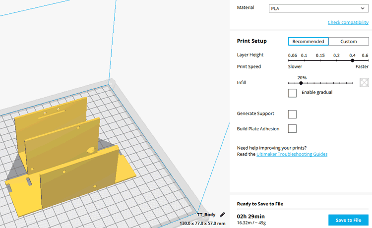
The parts have no overhanging structures, so you can easily print them without any supports, and an infill of 25% will work fine. The designs are pretty plain, and any basic printer should be able to handle them with ease. I used the Cura software to slice the model and printed using my Tevo Tarantula; the settings are shown below.
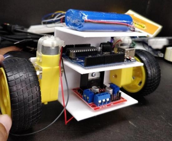
You would have to print the body part as well as four motor mounting parts. The assembly is pretty straightforward; use 3mm nuts and bolts to secure the motor and boards in place. After assembling it should look something like this shown in the picture below.
The actual design was planned with the L298N drive module in the bottom rack, the Arduino and battery on top of it, as shown above. If you are following the same order, you can directly screw the board through the holes provided and use a wire tag for the Li-po battery. This arrangement should also work, except for the super plain wheels, which I had to change later.
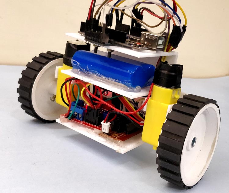
In my bot, I have swapped the position of the battery and Arduino UNO board for ease of programming and also had to introduce a perf board for completing the connections. So my bot did not look as I planned in the initial stage. After completing the wiring, programming, testing and everything, my two-wheel balancing robot finally looks like this
Self Balancing Robot Circuit Diagram Using Arduino Uno
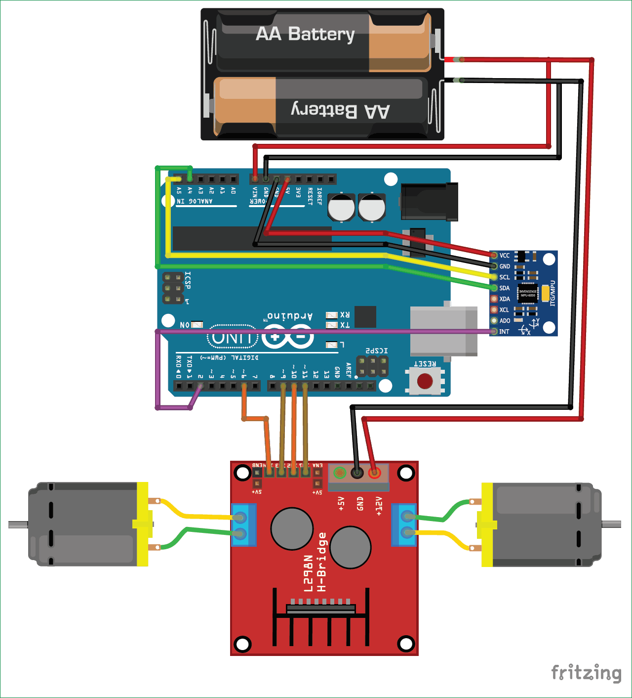
Making the connections for this Arduino based Self balancing Robot is pretty simple. This is a self balancing robot using Arduino and MPU6050, so we have to interface the MPU6050 with Arduino and connect the motors through the Motor driver module. The whole setup is powered by the 7.4V Li-ion battery. The circuit diagram for the same is shown below.
The self balancing robot circuit diagram above shows the whole connections between Arduino Uno, MPU6050 sensor, and L298N motor driver to build a self balancing robot. This Arduino self balancing robot circuit is designed to provide better performance and simple troubleshooting.
The Arduino and the L298N Motor driver module are directly powered through the Vin pin and the 12V terminal, respectively. The on-board regulator on the Arduino board will convert the input 7.4V to 5V, and the ATmega IC and MPU6050 will be powered by it. The DC motors can run from a voltage of 5V to 12V. But we will be connecting the 7.4V positive wire from the battery to the 12V input terminal of the motor driver module. This will make the motors operate with 7.4V. The following table will list how the MPU6050 and L298N motor driver module are connected to the Arduino.
The MPU6050 communicates with Arduino through the I2C interface, so we use the SPI pins A4 and A5 of Arduino. The DC motors are connected to PWM pins D6, D9, D10 and D11, respectively. We need to connect them to PWM pins because we will be controlling the speed of the DC motor by varying the duty cycle of the PWM signals. If you are not familiar with these two components, then it is recommended to read through the MPU6050 Interfacing and L298N Motor Driver tutorial.
Complete Self-Balancing Robot Arduino Code with PID Implementation
Now we have to program our Arduino UNO board to balance the robot. This is where all the magic happens; the concept behind it is simple. We have to check if the bot is leaning towards the front or the back using the MPU6050, and then if it’s leaning towards the front, we have to rotate the wheels in the forward direction, and if it is leaning towards the back, we have to rotate the wheels in the reverse direction.
At the same time, we also have to control the speed at which the wheels are rotating. If the bot is slightly disoriented from the centre position, the wheels rotate slowly, and the speed increases as it gets further away from the centre position. To achieve this logic, we use the PID algorithm, which has the centre position as the set-point and the level of disorientation as the output.
To know the current position of the bot, we use the MPU6050, which is a 6-axis accelerometer and gyroscope sensor combined. In order to get a reliable value of position from the sensor, we need to use the values of both the accelerometer and gyroscope, because the values from the accelerometer have noise problems, and the values from the gyroscope tend to drift with time. So we have to combine both and get the value of yaw, pitch and roll of our robot, of which we will use only the value of yaw.
Sounds a bit like head reeling, right? But worry not, thanks to the Arduino community, we have readily available libraries that can perform the PID calculation and also get the value of yaw from the MPU6050. The library is developed by br3ttb and jrowberg, respectively. Before proceeding, download their libraries from the following link and add them to your Arduino library directory.
https://github.com/br3ttb/Arduino-PID-Library/blob/master/PID_v1.h
https://github.com/jrowberg/i2cdevlib/tree/master/Arduino/MPU6050
Now that we have the libraries added to our Arduino IDE. Let’s start programming for our Self balancing Robot. Like always, the complete code for the MPU6050 balancing robot is given at the end of this page; here, I am just explaining the most important snippets in the code. A mentioned earlier, the code is built on top of the MPU6050 example code. We are just going to optimise the code for our purpose and add the PID and control technique for our self balancing robot.
First, we include the libraries that are required for this program to work. They include the in-built I2C library, PID Library and MPU6050 Library that we just downloaded.
Then we declare the variables that are required to get the data from the MPU6050 sensor. We read both the gravity vector and quaternion values and then compute the yaw, pitch and roll values of the bot. The float array ypr[3] will hold the final result.
In the next line, we initialise the PID algorithm by passing the input variables input, output, set point, Kp, Ki and Kd. Out of these, we have already set the values of set-point Kp, Ki and Kd in the above snippet of code. The value of input will be the current value of yaw that is read from the MPU6050 sensor, and the value of output will be the value that is calculated by the PID algorithm. So basically, the PID algorithm will give us an output value which should be used to correct the Input value to bring it close to the set point.
Inside the void setup function, we initialise the MPU6050 by configuring the DMP (Digital Motion Processor). This will help us in combining the Accelerometer data with the Gyroscope data and provide a reliable value of Yaw, Pitch and Roll. We will not go very deep into this since it will be far beyond the topic. Anyhow, one segment of code that you have to look up in the setup function is the gyro offset values. Each MPU6050 sensor has its values of offsets. You can use this Arduino sketch to calculate the offset value of your sensor and update the following lines accordingly in your program.
We also have to initialise the Digital PWM pins that we are using to connect our motors to. In our case, it is D6, D9, D10 and D11. So we initialise these pins as output pins and make them LOW by default.
Inside the main loop function, we check if the data from the MPU6050 is ready to be read. If yes, then we use it to compute the PID value and then display the input and output values of the PID on the serial monitor just to check how the PID is responding. Then, based on the value of the output, we decide if the bot has to move forward or backwards or stand still.
Since we assume that the MPU6050 will return 180 when the bot is upright. We will get positive correction values when the bot is falling towards the front, and we will get values in negative if the bot is falling towards the back. So we check for this condition and call the appropriate functions to move the bot forward or backwards.
The PID output variable also decides how fast the motor has to be rotated. If the bot is just about to fall, then we make a minor correction by rotating the wheel slowly. If these minor corrections didn't work and still if the bot is still falling, we increase the speed of the motor. The value of how fast the wheels rotate will be decided by the PI algorithm. Note that for the Reverse function, we have multiplied the value of the output by -1 so that we can convert the negative value to positive.
Arduino Self Balancing Robot Testing & PID Tuning Guide
Once you are ready with the hardware, you can upload the self-balancing robot Arduino code to your Arduino board. Make sure the connections are proper since we are using a Li-ion battery; extreme caution is needed. So double-check for short circuits and ensure that the terminals won’t come into contact even if your bot experiences some small impacts. Power up your module and open your serial monitor. If your Arduino can communicate with MPU6050 successfully and if everything is working as expected, you should see the following screen.
Here we see the input and output values of the PID algorithm in the format input => output. If the bot is perfectly balanced, the value of output will be 0. The input value is the current value from the MPU6050 sensor. The alphabet “F” represents that the bot is moving forward, and “R” represents that the bot is moving in reverse.
During the initial stages of PID, I recommend leaving your Arduino cable connected to the bot so that you can easily monitor the values of input and output, and also it will be easy to correct and upload your program for Kp, Ki and Kd values. The video below shows the complete working of the bot and also shows how to correct your PID values.
Technical Summary And GitHub Repository
A Technical Summary gives a summary of the purpose, development and main outcomes of the project. The GitHub Repository give you the complete source code and documentation. It provides a quick understanding and hands-on implementation for users and contributors.
Frequently Asked Questions on Arduino Self Balancing Robot
Software & tools
- Arduino IDE
- ROS
- Python
- OpenCV
- VS Code
Project demo video
What you get
- Working project / hardware kit, tested before delivery
- Complete source code with explanation
- Project demo and guidance for your viva
- Project report, PPT and IEEE paper support (on request)
Related ECE projects

Sustainable Battery Material For Electric Cars
Researchers have created eco-friendly batteries for EVs, matching cobalt-based batteries in cost-effectiveness with potential for lithium re...
View project
BorgWarner To Integrate STMicroelectronics SiC Technology In Viper Power Module For Volvo Cars Next-Generation EVs
STMicroelectronics will supply BorgWarner Inc. with the latest third generation 750V silicon carbide SiC power MOSFETs dice for their propri...
View project
Longer-Lasting Chips For Smartphones
New chips help users run apps faster, keep devices working longer, and handle more tasks on smartphones, computers, and cars.
View project
Battery Protection IC For Safer Cars
The IC makes backup power smaller using one lithium battery instead of many. It works in high heat and keeps automotive systems safe.
View project