


Obstacle Avoiding Car Using Arduino
Build your Obstacle Avoiding Robot Car Using Arduino using this easy to build circuit diagram and arduino code
- Suitable forB.Tech ECE students
- Build time5-7 weeks
- LevelAdvanced
- Available atAjvika Labs, Kakinada
About this project
Avoiding obstacles is a key job in robotics, where autonomous robots aim to reach their destination without bumping into things. One type of autonomous robot that's pretty clever is the real-time Arduino obstacle avoiding car . It can spot obstacles and figure out new paths to move without running into them. Previously, we have built many robots using Arduino, including an Obstacle Avoiding Robot using Arduino Uno and an Ultrasonic Sensor. You can also check them out if you are interested. This thorough guide will teach you how to build an obstacle-avoiding vehicle using readily available components. An obstacle avoiding robot car autonomously navigates its environment by detecting obstacles with sensors and intelligently changing direction to avoid collisions.
In this comprehensive guide, I will explain the process of constructing your very own obstacle avoiding car using Arduino. This innovative vehicle employs a servo-mounted ultrasonic sensor to detect objects situated both in front and on either side of the car. Additionally, it employs an L298N DC motor driver, which serves as the driving force for four geared motors. You also need an Arduino obstacle avoiding car kit for this project. In this detailed obstacle avoiding car project, you'll learn to build a fully functional autonomous robot that uses an HC-SR04 ultrasonic sensor mounted on a servo motor for 180-degree environmental scanning. This tutorial provides the complete Arduino obstacle avoiding car code, a detailed obstacle avoiding car circuit diagram, and step-by-step assembly instructions.
What is an Arduino Obstacle Avoiding Car?
Understanding the Circuit Design
Step-by-Step Wiring Connections
Power Supply Connections
Real-World Applications
What is an Arduino Obstacle Avoiding Car?
An Arduino obstacle avoiding car is an autonomous mobile robot that's designed to identify obstacles that are in its way and make decisions to navigate around them without the need for human involvement. This robot uses an ultrasonic distance sensor along with a distance-measured ultrasonic distance sensor to detect the proximity of nearby objects. The information is processed and compiled together in an Arduino microcontroller to direct two DC motors to move away from an obstacle. This technology provides the foundations for autonomous vehicles, robotic vacuum cleaners, autonomous machines and educational robotic systems.
Some of the main components of an obstacle avoiding robot car are as follows: a brain (opto-isolated Arduino Uno microcontroller), a sensory system to detect the proximity of obstacles (an HC-SR04 ultrasonic sensor on a rotating servo mount), a motor control system (an L298N dual H-bridge driver), a propulsion system (four DC geared motors), power management (a battery: 12V Li-ion batteries with voltage regulation circuit) and a power supply. When combined, these systems created an intelligent machine capable of decision making, judgment, and autonomous navigational control with few restrictive obstacles in its way.
Components Required for Obstacle Avoiding Car Project
To build this obstacle avoiding car project, you'll need the following components. These parts are readily available online through electronics retailers, and many suppliers offer complete obstacle avoiding car kits that include all necessary components.
MG 90 metal gear Servo motors (1x)
HC-SR04 Ultrasonic Sensor
2WD Arduino car kit, Laser cut Chassis
LM2596 DC-DC buck converter
Breadboard or PCB (Printed Circuit Board)
Screws, nuts, spacers
Arduino Obstacle Avoiding Car Circuit Diagram
The complete circuit diagram for this 2WD obstacle avoiding robot is given below. As you can see, it uses an Ultrasonic sensor to take measurements in all three directions with the help of a servo motor. Based on the distance measurements, the motor takes actions to move forward or turn left and right. The complete obstacle avoiding car circuit diagram is shown below.
Understanding the Circuit Design
The HC-SR04 ultrasonic sensor plays a crucial role in this Arduino obstacle avoiding car. It transmits 40kHz ultrasonic pulses that reflect off objects and return as echoes. The sensor plays a crucial role in this project. It sends out 40kHz ultrasonic signals that bounce back when they hit an object. By analysing the returning echoes, the sensor calculates distances between the car and obstacles in real-time. When an obstacle is detected, the car autonomously changes direction. Once our Arduino car for obstacle avoidance is built, it should look like something as shown in the image below.
The L298N motor driver controls the four DC motors that propel the obstacle avoiding robot car. We have used an off-the-shelf Robotic Car chassis kit to build the body of our robot. There are many versions of the Arduino robot kit available on the market. You can purchase the now of your choice. But we personally selected this kit because it looks more like a car with a front bumper, spoiler, etc. Previously, we have also used the same kit to build other projects like the Human Following Robot and Pick and Place Arduino Robot Car. You can also check them out if you are interested.
Step-by-Step Wiring Connections for Obstacle Avoiding Car
Building the Arduino obstacle avoiding car requires careful attention to wiring connections. Follow these detailed instructions to ensure proper circuit assembly. To make things easy to understand, in the following paragraphs, we have explained how each component is connected to the Arduino Nano. You can also follow the circuit diagram for better understanding.
Servo Motor Connection with Arduino
To connect the servo motor to the Arduino, simply attach the signal wire to any PWM control pin, connect the power wire to the 5V output from a DC-DC converter, and link the ground wire to one of the Arduino's ground pins.
Connecting Arduino Car to Ultrasonic Sensor
Connect the sensor to the Arduino like this: VCC to 5V, GND to GND, TRIG to a digital pin 2, and ECHO to another digital pin 4 of. This setup allows the Arduino to interact with the sensor. Further, we will also be writing an arduino car ultrasonic sensor code to enable our robot to read the distance of objects ahead of it and control the wheels accordingly. More details on that can be found in the code section.
RGB LEDs Connection with Arduino
Connect all the RGB LEDs' ground (cathode) to a ground rail on the breadboard. Then, link each RGB LED's red terminal to an analog pin on the Arduino(A1, A2&A3) and the green terminal to a digital pin on the Arduino(5,6&13). This configuration allows the Arduino to control the RGB LEDs.
L298N Motor Driver Connection with Arduino
Arduino's GND to breadboard GND rail, Arduino's Vin to breadboard positive rail, LM2596 5V out to positive rail, LM2596 GND out to GND rail. For the DC motor, 1 L298N IN1 and IN2 to Arduino pins 7 and 8. For the DC motor, 2 L298N IN3 and IN4 to Arduino pins 12 and 11. Enable PWM motor control by connecting L298N ENA to Arduino PWM pin 9 and ENB to PWM pin 10, enabling independent control of two DC motors using Arduino.
Power Supply Connections and Distribution
Connect the 12V Li-ion battery's positive terminal to the LM2596's Vin input and link the battery's negative terminal to the breadboard's ground rail. Also, connect the battery's positive terminal to the L298N motor driver's 12V input and connect the battery's negative terminal to the L298N's GND.
Importan t: Always turn off the Arduino power switch and remove the external Vin supply when you upload the code.
Secure all components to the car frame using screws, nuts, and spacers as needed. Ensure that all connections are secure and free from loose wires or potential short circuits. Always double-check your connections before powering on the circuit.
Additionally, I incorporated several enhancements to the car's design. These include the addition of a power on/off switch, a 12V DC charging socket, and a Li-ion battery level indicator located on the back side of the vehicle. Furthermore, I included a slider switch near the DC socket, which serves the purpose of monitoring the battery level when the primary power switch is off. When it comes to charging the battery, you simply slide the switch upwards. Conversely, if you wish to check the charging status of the battery, you can easily slide the switch back down. Do note that, when the switch is slid down, it will not charge the battery.
Arduino Obstacle Avoiding Car Code Explained
The Arduino obstacle avoiding car code below provides complete functionality for autonomous navigation. Now that the obstacle avoiding car connection is complete, let’s have a look at the Arduino obstacle avoiding car code. The complete Arduino code for obstacle avoiding car is given at the end of this page. The program will include setting up the HC-SR04 module and outputting the signals to the Motor Pins to move the motor direction accordingly. Copy the complete obstacle avoiding car code provided below.
You can make some personal changes in the code, like the threshold distance as per your requirement and motor speed control. Install the required libraries and upload the code given above.
In this block, various pin constants are defined for components such as the Ultrasonic sensor and RGB LEDs. These constants are used to specify which pins on the Arduino are connected to each component.
These lines define digital pins of Arduino (pin7, pin8, pin12 and pin11) for the L298N motor driver inputs to control the DC motors. The pins in1 and in2 control one motor, and the pins in3 and in4 control the other motor. Ena and Enb control the speed of the motor.
This block defines threshold values. MIN_DISTANCE_BACK represents the minimum distance required from an obstacle to stop.
In the setup() function, various initialisations take place. This includes configuring motor control pins, LED pins, and sensor pins as either OUTPUT or INPUT. It also sets the initial states for LEDs and RGB LEDs to LOW or 0. Additionally, the Servo motor is attached to pin 5, motor speed is adjusted using analogWrite() for ENA and ENB, and serial communication is initiated for debugging (though this part is optional).
This is the main loop of the code, executed continuously. The servo motor is set to look straight ahead, and there's a delay for it to settle. The getDistance() function is used to measure the distance using the Ultrasonic sensor. If the measured distance is greater than or equal to MIN_DISTANCE_BACK, the robot is instructed to move forward. While the distance is above the threshold, it continues moving forward. When the distance becomes less than MIN_DISTANCE_BACK, the Stop() function is called to stop the robot. The checkDirection() function is used to determine if there's an obstacle in the left, right, or front direction. Based on the detected direction, the robot will turn left, turn right, or move forward. Serial messages are printed to help with debugging.
This function measures the distance to an object using the Ultrasonic sensor. It generates a trigger pulse and measures the time for the pulse to return. Calculate and return the distance based on the measured time.
int checkDirection() //Check the left, Front and right directions and decide which way to turn
This section of the code handles the obstacle-avoidance strategy for the car's movement. It continually monitors obstacle distances in three directions: left, right, and front by utilising a servo motor. After each scan, it calculates the distances to nearby obstacles. If both the left and right directions have close obstacles, the car proceeds forward. If there's more space on the left side, it steers the car left, and if the right side is more open, it directs the car to the right. If all three directions (front, left, and right) have obstructions nearby, the car is instructed to perform a U-turn. These directions are communicated by returning specific values: 0 for left, 2 for right, 3 for forward, and 1 for turning around.
These blocks are used in the main Arduino obstacle avoiding car code 2WD to control the car's movement and direction based on obstacle detection and the desired action.
moveForward() This function makes the car move forward. It sets the motor speeds for both sides to move forward, turns on green lights (indicating forward movement), and turns off red lights (indicating stopping or backward movement).
moveBackward() This function makes the car move backwards. It turns off the green lights and turns on the red lights to indicate reverse motion. It also sets the motor speeds for backward movement.
turnRight() This function makes the car turn right. It adjusts the motor speeds to execute a right turn, turns on the right-side green light, and turns on the left and middle red lights to indicate the right turn.
turnLeft() This function makes the car turn left. It adjusts the motor speeds to execute a left turn, turns on the left-side green light, and turns on the right and middle red lights to indicate the left turn.
Stop(). This function brings the car to a complete stop. It turns off all lights (indicating a stop), sets both motor speeds to zero, and stops all motor movement.
Common Issues and Troubleshooting
The The Car doesn't move when powered on
Verify battery voltage is above 11V using a multimeter
Verify battery voltage is above 11V using a multimeter
Check all motor driver connections (IN1–IN4, ENA, ENB)
Technologies used
Hardware components
- Arduino
- Servo Motor
- DC Motor
- L298N
- Ultrasonic Sensor
- ESP32
Software & tools
- Arduino IDE
- ROS
- Python
- OpenCV
- VS Code
Project demo video
What you get
- Working project / hardware kit, tested before delivery
- Complete source code with explanation
- Project demo and guidance for your viva
- Project report, PPT and IEEE paper support (on request)
Delivery & Payment
Delivery takes a minimum of two weeks from the date your inquiry is confirmed.
Payment is in two parts:
• 50% advance to start the project
• Remaining 50% before delivery
Note:
• Documentation and PPT are not included by default
• If you need documentation/PPT, it can be arranged for extra time and cost
We'll confirm the exact timeline and cost with you after reviewing your requirements.
Related ECE projects
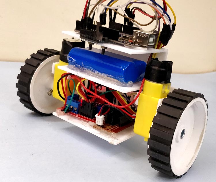
ECE
DIY Self Balancing Robot using Arduino
In this tutorial I will document my experience in building the self balancing robot. You might be an absolute beginner who is just getting s...
View project
ECE
Sustainable Battery Material For Electric Cars
Researchers have created eco-friendly batteries for EVs, matching cobalt-based batteries in cost-effectiveness with potential for lithium re...
View project
ECE
BorgWarner To Integrate STMicroelectronics SiC Technology In Viper Power Module For Volvo Cars Next-Generation EVs
STMicroelectronics will supply BorgWarner Inc. with the latest third generation 750V silicon carbide SiC power MOSFETs dice for their propri...
View project
ECE
Longer-Lasting Chips For Smartphones
New chips help users run apps faster, keep devices working longer, and handle more tasks on smartphones, computers, and cars.
View project