

Interfacing DRV8833 Dual Motor Driver Module with Arduino
In this tutorial, we will Interface DRV8833 Dual Motor Driver Module with Arduino. With this project, we are going to control the speed and direction of dc motor.
- Suitable forB.Tech ECE students
- Build time5-7 weeks
- LevelAdvanced
- Available atAjvika Labs, Kakinada
About this project
If you are interested in building robots, then it is certain that you need to learn how to control the speed and direction of a DC motor, and in one of our previous tutorials, we did just that using the popular L293D Motor Driver IC and ESP32. However, there is a different IC called DRV8833, which is also a dual drive motor driver solution and is cheaper than the L293D IC. So in this project, we will be interfacing the DRV8833 Arduino, while we will also know everything about this DRV8833 module. Here we used Arduino Pro Mini; however, any Arduino model can be used to build this drv8833 arduino project.
DRV8833 Dual Motor Driver with Arduino - Quick Overview
Build Time: 2-4 hours | Cost: $15-30 | Difficulty: Beginner-Intermediate
What You'll Learn: PWM speed control, H-bridge direction control, Arduino motor interfacing, Basic schematic wiring
Applications: Robot locomotion, DC motor projects, Stepper motor driving, Solenoid/relay control
Controlling DC Motors with Microcontrollers
DRV8833 Motor Driver IC Overview
Pinout and Wiring Diagram
Commonly Asked Questions
Simple Circuit Diagram
└ Overheating Solutions
Controlling DC Motors with Microcontrollers
To get complete control of the motor, we need to take control of the speed and direction of the motor, and to do that, we need to use Pulse Width Modulation or PWM Technique to control the speed, and we are going to use the internal H-bridge to control the direction of the motor. We previously did a basic DC motor control using Arduino and the PWM technique.
PWM - Motor Speed Control
When we are talking about a DC motor, to change the speed of the DC motor, we need to change the amplitude of the input voltage that is applied to the motor. A common technique to do that is PWM (Pulse Width Modulation). In PWM, the applied voltage is adjusted by sending a series of pulses, so the output voltage is proportional pulse width generated by the microcontroller, which is also known as the duty cycle. We have explained Pulse width modulation in detail earlier. Also, check more PWM based projects with other microcontrollers by following the link.
The higher the duty cycle, the higher the average voltage applied to the DC motor (resulting in higher speed) and the shorter the duty cycle, the lower the average voltage applied to the DC motor (resulting in lower speed).
H-Bridge Motor Direction Control
To change the direction of rotation of a DC motor, you need to change the polarity of the supply. A common technique to do that is by using an H-bridge motor driver. An H-bridge motor driver consists of four switches (usually MOSFETs) arranged in a certain formation, and the motor is connected to the centre of the arrangement to form the H-like structure.
By closing/enabling two opposite switches, we can change the direction of the flowing current, thus changing the direction of rotation.
DRV8833 Motor Driver IC Overview
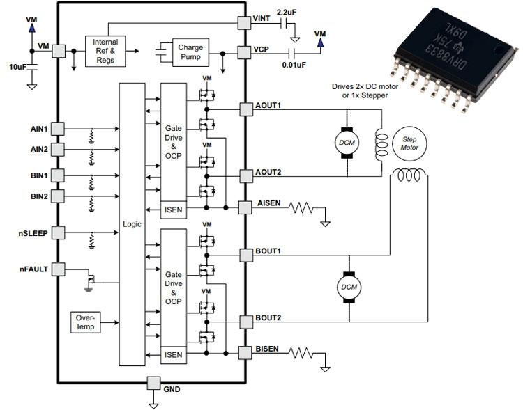
The DRV8833 motor driver IC is a dual-channel motor drive IC capable of driving two bidirectional motors or a single stepper motor. The output driver block of each H-bridge consists of N-channel power MOSFETs configured as an H-bridge to drive the motor windings. Each H-bridge includes circuitry to regulate or limit the winding current. This DRV8833 dual motor driver is also designed to drive inductive loads such as relays, solenoids, DC, and bipolar stepping motors.
The internal structure of the DRV8833 motor driver IC is shown above, and it's taken from the DRV8833 dataset of the device. The device integrates two NMOS H-bridges and current regulation circuitry. The DRV8833 module can be powered with a supply voltage from 2.7 to 10.8 V and can provide an output current up to 1.5-A RMS. The device also includes a low-power sleep mode, which lets the system save power when not driving the motor.
DRV8833 Module Pinout and Wiring Diagram
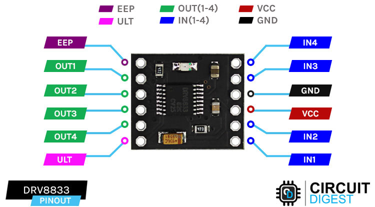
The DRV8833 pinout of the DRV8833 motor driver module is shown below. The DRV8833 module has a total of 12 pins that can be connected to the microcontroller and motor for complete drv8833 arduino interfacing.
EEP, this is the sleep pin for the DRV8833 motor driver module. Logic high to enable the device, logic low to enter low-power sleep mode and reset all
OUT(1-2) Output1 and Output2 of the internal H-Bridge A.
OUT(3-4) Output1 and Output2 of the internal H-Bridge B.
IN(1-2) Input1 and Input2 of the internal H-Bridge A for drv8833 arduino control signals
IN(3-4) Input3 and Input4 of the internal H-Bridge B for DRV8833 motor driver Arduino control signals
ULT Fault pin of the IC. Logic low when in fault condition (overtemperature, overcurrent)
VCC Supply pin of the IC. Max Operating Voltage: 11.8V for for drv8833 module.
GND Ground pin of the IC connects it to the supply Ground.
DRV8833 Motor Driver IC Module Parts
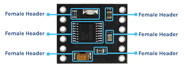
The parts marking of the DRV8833 module is shown below. The module is made with generic components, and in this action, it is shown below.
As you can see in the image above, in the middle of the module, we have our DRV8833 IC, and there are mainly three bypass capacitors on the board: a 10uF tantalum capacitor for input power. A 2.2uF capacitor for the VINT Pin and a 0.1uF capacitor for the VCP Pin. Finally, we have the onboard power indicator with its 4.7K Current limiting resistor.
Schematic Diagram of the DRB8833 Module
The internal schematic diagram of the DRV8833 module is shown below. The circuit diagram of the module is very simple, as it has very few components on the PCB.
As you can see in the schematic diagram, the connection for all the bypass capacitors to the IC is shown. We have also shown the connection for the pin header, and beside the header, you can see the names of the pins in the PCB. On the PCB, there is also an LED with a current-limiting resistor as an indicator.
Commonly Asked Questions about DRV8833 Motor Driver IC
⇥ What is the difference between L293D and DRV8833? The L293D and the DRV8833 are both motor driver ICs, but they have differences. Both the ICs have a maximum current of 1.5A, but the operating voltage of the DRV8833 IC is 11.8V, whereas the operating voltage of the L293D is 40V.
⇥ Can I run the stepper motor with DRV8833? Yes, the DRV8833 IC can drive stepper motors. But micro-stepping is not possible with this IC; for that, you will need a dedicated driver IC.
⇥ Can I connect 4 motors to DRV8833? The DRV8833 is designed to drive two DC motors. If you want to drive 4 motors, it may still be feasible if you sacrifice direction control.
⇥ What is the DRV8833 motor driver used for? It is the DRV8833 motor driver IC intended for use with DC motors and stepper motors with Arduino or some other microcontroller. The DRV8833 allows control of motors in either direction with PWM speed control up to 1.5 Amp RMS current and a voltage supply range from 2.7V to 10.8V.
⇥ How do you wire the DRV8833 with Arduino? Connect the IN1 to IN4 pins of DRV8833 to Arduino digital pins (9, 6, 5, 3), VCC to the 5V supply, GND to ground, and the motor terminals to the OUT1-OUT4 pins. The wiring diagram shows the enable pin (EEP) tied high for the driver module, which is a must in most cases.
⇥ So, what are some distinctions between the DRV8833 and L293D? The main differences between DRV8833 and L293D are, the DRV8833 uses a MOSFET H-bridge design, whereas L293D uses bipolar transistors. Low-drop-out MOSFET means less heat is dissipated with lower voltage drop when using the L293D DC motor drive. And as a matter of fact, DRV8833 provides current sensing and regulation. However, if you need to control higher voltage (and higher power) applications that require the higher-rated voltage (36 V vs. 10.8 V typically advertised with the DRV8833), it is not as fast acting and more prefer L293D.
Simple Circuit Diagram: DRV8833 Interfacing with Arduino
The schematic diagram of the DRV8833 Module interfacing with Arduino is shown below.
The DRV8833 motor driver wiring diagram shows the DRV8833 Arduino interfacing to the Arduino Pro Mini. As shown in the diagram, pins 9,6,5,3 are connected to the IN1, IN2, IN3, and IN4 pins of the DRV8833 module, respectively, and the output pins are connected to the two motors. A switch is connected to pin 10 of the Arduino Pro Mini, and this switch is used to change the direction of rotation. There are two potentiometers to adjust the speed of the motors. The circuit is powered by an 8.4V battery. Lastly, there is a switch to control the direction of the motors. The Hardware setup of the DRV8833 module is shown below.
If your DRV8833 module is getting excessively hot during operation, implement these solutions:
Add heatsink, reduce motor load
Overcurrent condition
Check motor stall, add current limiting
Power supply voltage drop
Use larger capacity battery/supply
Add 0.1μF capacitors across motor terminals
Arduino Code for Interfacing the DRV8833 Motor Driver IC with Arduino
Complete code for Arduino DC motor speed control using PWM is given below. Here, we are explaining the code in detail.
Now that we have a clear understanding of how the DRV8833 Module works, we can write some code to control the speed and direction of the motor.
We start our code by defining all the pins for the motor driver and the switches.
Next, we have our setup function. In the setup function, we make the PWM pins as outputs and the switch pins as inputs, and we set all the pins low.
DRV8833 Dual Motor Driver with Arduino - Quick Overview
Build Time: 2-4 hours | Cost: $15-30 | Difficulty: Beginner-Intermediate
What You'll Learn: PWM speed control, H-bridge direction control, Arduino motor interfacing, Basic schematic wiring
Applications: Robot locomotion, DC motor projects, Stepper motor driving, Solenoid/relay control
Controlling DC Motors with Microcontrollers
DRV8833 Motor Driver IC Overview
Pinout and Wiring Diagram
Commonly Asked Questions
Simple Circuit Diagram
└ Overheating Solutions
Controlling DC Motors with Microcontrollers
To get complete control of the motor, we need to take control of the speed and direction of the motor, and to do that, we need to use Pulse Width Modulation or PWM Technique to control the speed, and we are going to use the internal H-bridge to control the direction of the motor. We previously did a basic DC motor control using Arduino and the PWM technique.
PWM - Motor Speed Control
When we are talking about a DC motor, to change the speed of the DC motor, we need to change the amplitude of the input voltage that is applied to the motor. A common technique to do that is PWM (Pulse Width Modulation). In PWM, the applied voltage is adjusted by sending a series of pulses, so the output voltage is proportional pulse width generated by the microcontroller, which is also known as the duty cycle. We have explained Pulse width modulation in detail earlier. Also, check more PWM based projects with other microcontrollers by following the link.
The higher the duty cycle, the higher the average voltage applied to the DC motor (resulting in higher speed) and the shorter the duty cycle, the lower the average voltage applied to the DC motor (resulting in lower speed).
H-Bridge Motor Direction Control
To change the direction of rotation of a DC motor, you need to change the polarity of the supply. A common technique to do that is by using an H-bridge motor driver. An H-bridge motor driver consists of four switches (usually MOSFETs) arranged in a certain formation, and the motor is connected to the centre of the arrangement to form the H-like structure.
By closing/enabling two opposite switches, we can change the direction of the flowing current, thus changing the direction of rotation.
DRV8833 Motor Driver IC Overview
The DRV8833 motor driver IC is a dual-channel motor drive IC capable of driving two bidirectional motors or a single stepper motor. The output driver block of each H-bridge consists of N-channel power MOSFETs configured as an H-bridge to drive the motor windings. Each H-bridge includes circuitry to regulate or limit the winding current. This DRV8833 dual motor driver is also designed to drive inductive loads such as relays, solenoids, DC, and bipolar stepping motors.
The internal structure of the DRV8833 motor driver IC is shown above, and it's taken from the DRV8833 dataset of the device. The device integrates two NMOS H-bridges and current regulation circuitry. The DRV8833 module can be powered with a supply voltage from 2.7 to 10.8 V and can provide an output current up to 1.5-A RMS. The device also includes a low-power sleep mode, which lets the system save power when not driving the motor.
DRV8833 Module Pinout and Wiring Diagram
The DRV8833 pinout of the DRV8833 motor driver module is shown below. The DRV8833 module has a total of 12 pins that can be connected to the microcontroller and motor for complete drv8833 arduino interfacing.
EEP, this is the sleep pin for the DRV8833 motor driver module. Logic high to enable the device, logic low to enter low-power sleep mode and reset all
OUT(1-2) Output1 and Output2 of the internal H-Bridge A.
OUT(3-4) Output1 and Output2 of the internal H-Bridge B.
IN(1-2) Input1 and Input2 of the internal H-Bridge A for drv8833 arduino control signals
IN(3-4) Input3 and Input4 of the internal H-Bridge B for DRV8833 motor driver Arduino control signals
ULT Fault pin of the IC. Logic low when in fault condition (overtemperature, overcurrent)
VCC Supply pin of the IC. Max Operating Voltage: 11.8V for for drv8833 module.
GND Ground pin of the IC connects it to the supply Ground.
DRV8833 Motor Driver IC Module Parts
The parts marking of the DRV8833 module is shown below. The module is made with generic components, and in this action, it is shown below.
As you can see in the image above, in the middle of the module, we have our DRV8833 IC, and there are mainly three bypass capacitors on the board: a 10uF tantalum capacitor for input power. A 2.2uF capacitor for the VINT Pin and a 0.1uF capacitor for the VCP Pin. Finally, we have the onboard power indicator with its 4.7K Current limiting resistor.
Schematic Diagram of the DRB8833 Module
The internal schematic diagram of the DRV8833 module is shown below. The circuit diagram of the module is very simple, as it has very few components on the PCB.
As you can see in the schematic diagram, the connection for all the bypass capacitors to the IC is shown. We have also shown the connection for the pin header, and beside the header, you can see the names of the pins in the PCB. On the PCB, there is also an LED with a current-limiting resistor as an indicator.
Commonly Asked Questions about DRV8833 Motor Driver IC
⇥ What is the difference between L293D and DRV8833? The L293D and the DRV8833 are both motor driver ICs, but they have differences. Both the ICs have a maximum current of 1.5A, but the operating voltage of the DRV8833 IC is 11.8V, whereas the operating voltage of the L293D is 40V.
⇥ Can I run the stepper motor with DRV8833? Yes, the DRV8833 IC can drive stepper motors. But micro-stepping is not possible with this IC; for that, you will need a dedicated driver IC.
⇥ Can I connect 4 motors to DRV8833? The DRV8833 is designed to drive two DC motors. If you want to drive 4 motors, it may still be feasible if you sacrifice direction control.
⇥ What is the DRV8833 motor driver used for? It is the DRV8833 motor driver IC intended for use with DC motors and stepper motors with Arduino or some other microcontroller. The DRV8833 allows control of motors in either direction with PWM speed control up to 1.5 Amp RMS current and a voltage supply range from 2.7V to 10.8V.
⇥ How do you wire the DRV8833 with Arduino? Connect the IN1 to IN4 pins of DRV8833 to Arduino digital pins (9, 6, 5, 3), VCC to the 5V supply, GND to ground, and the motor terminals to the OUT1-OUT4 pins. The wiring diagram shows the enable pin (EEP) tied high for the driver module, which is a must in most cases.
⇥ So, what are some distinctions between the DRV8833 and L293D? The main differences between DRV8833 and L293D are, the DRV8833 uses a MOSFET H-bridge design, whereas L293D uses bipolar transistors. Low-drop-out MOSFET means less heat is dissipated with lower voltage drop when using the L293D DC motor drive. And as a matter of fact, DRV8833 provides current sensing and regulation. However, if you need to control higher voltage (and higher power) applications that require the higher-rated voltage (36 V vs. 10.8 V typically advertised with the DRV8833), it is not as fast acting and more prefer L293D.
Simple Circuit Diagram: DRV8833 Interfacing with Arduino
The schematic diagram of the DRV8833 Module interfacing with Arduino is shown below.
The DRV8833 motor driver wiring diagram shows the DRV8833 Arduino interfacing to the Arduino Pro Mini. As shown in the diagram, pins 9,6,5,3 are connected to the IN1, IN2, IN3, and IN4 pins of the DRV8833 module, respectively, and the output pins are connected to the two motors. A switch is connected to pin 10 of the Arduino Pro Mini, and this switch is used to change the direction of rotation. There are two potentiometers to adjust the speed of the motors. The circuit is powered by an 8.4V battery. Lastly, there is a switch to control the direction of the motors. The Hardware setup of the DRV8833 module is shown below.
If your DRV8833 module is getting excessively hot during operation, implement these solutions:
Add heatsink, reduce motor load
Overcurrent condition
Check motor stall, add current limiting
Power supply voltage drop
Use larger capacity battery/supply
Add 0.1μF capacitors across motor terminals
Arduino Code for Interfacing the DRV8833 Motor Driver IC with Arduino
Complete code for Arduino DC motor speed control using PWM is given below. Here, we are explaining the code in detail.
Now that we have a clear understanding of how the DRV8833 Module works, we can write some code to control the speed and direction of the motor.
We start our code by defining all the pins for the motor driver and the switches.
Next, we have our setup function. In the setup function, we make the PWM pins as outputs and the switch pins as inputs, and we set all the pins low.
Technologies used
Hardware components
- Arduino
- Servo Motor
- DC Motor
- L298N
- Ultrasonic Sensor
- ESP32
Software & tools
- Arduino IDE
- ROS
- Python
- OpenCV
- VS Code
Project demo video
What you get
- Working project / hardware kit, tested before delivery
- Complete source code with explanation
- Project demo and guidance for your viva
- Project report, PPT and IEEE paper support (on request)
Delivery & Payment
Delivery takes a minimum of two weeks from the date your inquiry is confirmed.
Payment is in two parts:
• 50% advance to start the project
• Remaining 50% before delivery
Note:
• Documentation and PPT are not included by default
• If you need documentation/PPT, it can be arranged for extra time and cost
We'll confirm the exact timeline and cost with you after reviewing your requirements.
Related ECE projects
ECE
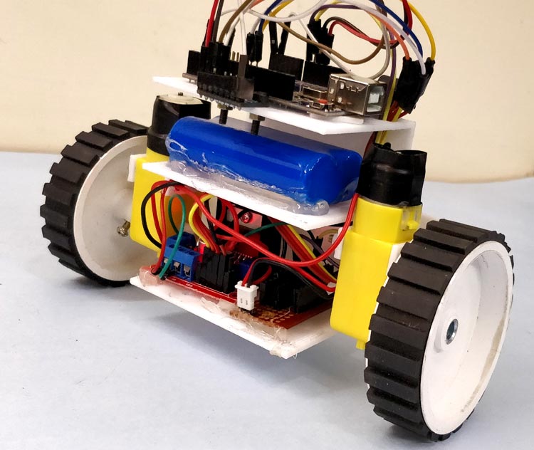
DIY Self Balancing Robot using Arduino
In this tutorial I will document my experience in building the self balancing robot. You might be an absolute beginner who is just getting s...
View project
ECE
Sustainable Battery Material For Electric Cars
Researchers have created eco-friendly batteries for EVs, matching cobalt-based batteries in cost-effectiveness with potential for lithium re...
View project
ECE
BorgWarner To Integrate STMicroelectronics SiC Technology In Viper Power Module For Volvo Cars Next-Generation EVs
STMicroelectronics will supply BorgWarner Inc. with the latest third generation 750V silicon carbide SiC power MOSFETs dice for their propri...
View project
ECE
Longer-Lasting Chips For Smartphones
New chips help users run apps faster, keep devices working longer, and handle more tasks on smartphones, computers, and cars.
View project