


DIY Fire Fighting Robot using Arduino and Ultrasonic Sensor
In this project, we will make a fire fighting robot using arduino. This fire fighting robot can be used in the modern world which navigates areas and extinguishes fire in a given environment with avoiding any obstacles it faces in its.
- Suitable forB.Tech ECE students
- Build time5-7 weeks
- LevelAdvanced
- Available atAjvika Labs, Kakinada
About this project
Thus, to combat the situation instead of human beings, fire fighting robots are used in the modern world which navigates the area and extinguishes the fire in a given environment with avoiding any obstacles it faces in its. The principle used in the design is such that it enables the robot to be extended for a more robust system which is to be used to combat actual fires in residential or commercial settings of the area. The main purpose of this arduino project is to create a fully autonomous robot, which means, once the robot is started by the user, it navigates, it searches, and extinguishes the fire on its own, with no assistance or input from the user, with giving an alert message to your phone number and also avoids obstacles in its way. In order to reach this goal, I have selected motors, sensors, fire extinguisher mechanical parts, and general design according to the requirement of the robot. For future scope and for a large system, a replica of the same robot to a large scale with fire-resistant material so that robot cannot be harmed through fire and prevents any cause of harm to humans and properties at an accurate timing level could be made.
Previosly, we made many robotic projects, including the Arduino based fire Fighting Robot :
DIY Arduino Bluetooth Car Controlled by Mobile Application
Raspberry Pi based Autonomous UV Robot with SLAM
Obstacle Avoiding Robot using Arduino, Servo Motors and Ultrasonic Sensor
Building an easy Line Follower Robot using Arduino Uno
Component Required for Fire Fighting Robot
Project Used Hardware
Arduino UNO/ Arduino mega 2560r3, Flame sensors [(x 3 pieces) out of which 1 has 4-pins and other 2 has 3-pins], Servo Motor (SG90)[x2 pieces ], L298N motor Driver module, Mini DC Submersible Pump, Robot chassis with 4 motors and 4 wheels, A small container, Connecting wires, jumper wires, Water tube, Relay module(5v 1 channel), Batteries(4 li-ion 3.7v 18650 à 3 used in series to make 12v supply and 1 battery is used to power on gsm module, Switch, BMS board, Ultrasonic sensor (HC-SR04), Battery holder, GSM 800l module, 2g sim card, 1kohm, and 2kohm resistors, soldering machine, soldering wire, wire cutter, screw driver, glue sticks and glue gun and some small screws and nuts.
Project Used Software
Project Hardware Software Selection
The main brain of this project is Arduino UNO/Mega depending upon applicating features. In my case, I‘m using the gsm module as features are more all pins of Arduino UNO are full so Arduino mega is used. But I cannot find 2g sim card anywhere so without 2g sim card, the alert message feature is useless so without the SMS feature Arduino UNO can be used. L298n motor driver is used to run the 4 motors of the robot. L293d motor driver shield has only some pins left for Arduino so here l298n is used rather than l293d for efficient use of all pins. You can also check how to use L298N Motor Driver with Arduino UNO if you want to learn more about this motor driver module.
2 motors of two directions (left, right) are connected parallelly to run all 4 motors. Relay of 5v 1 channel is used to on/off the pump for water flow, for that 9v battery is used. The ultrasonic sensor is used to detect obstacles, with that two servo motors are used one for the obstacle to detecting an obstacle in both directions and the other is for water tube moves up and down. 3 flame sensors are used to detect fire in all 3 directions à left, center, right out of which the center should be of 4 pins so that the fourth pin is of analog pin used to calculate the distance of fire from the robot. Gsm 800l module is used with 2g sim card properly inserted and connected according to the circuit diagram. Arduino IDE software is used to write and admin/upload the code to Arduino.
According to the circuit diagram shown, Arduino mega is here the main component. The left flame sensor is connected to pin 2, the right flame sensor is connected to pin 3, center flame sensor is connected to pin4. The center flame sensor if using has 4 pins àvcc, gnd, d0, a0 then a0 (analog) pin of the sensor goes to a1 analog pin of Arduino and d0 goes to digital pin 4 of Arduino and vcc and gnd are connected together with all vcc gnd pins of other components and finally Vcc and GND iof that is connected to Arduino. IN1, IN2, IN3, IN4 of L298n motor driver are connected to digital pin numbers 9,10,11,12 respectively. moto1 out point of the driver is connected to any 2 motors that are parallelly connected of any direction similarly with motor 2 out. check the polarity of motors as both mot1 and mot2 ports has to be connected with the same polarity. So that when the forward function is called by Arduino then all four motors move in forwarding directions. signal pin of the relay goes to pin 5. 9v battery positive and pump positive both go to no and common pin of relay respectively. Both negatives are interconnected. Now signal of servo of the water tube is connected to pin no 6 and the signal of servo of the obstacle is connected to pin no 7. Trigger pin of hc -sr04 ultrasonic sensor is connected analog pin a2 of Arduino and echo pin of ultrasonic sensor is connected to analog pin a3 of Arduino. All +5v and grounds are connected together and then connected to 5v and gnd of arduino. Make 12v power supply by connecting 3 li-ion 3.7v in series, the positive of it goes to +12v of l298n through switch and ground to gnd of l298n, connect +5v and gnd of l298n to +5v and gnd of Arduino. Connect +5v and gnd of gsm to 3.7v 18650 li-ion battery. Insert 2g sim card properly as shown in the picture. Now connect TX of gsm to digital pin 14 of Arduino and RX of gsm to digital pin 15 of Arduino with 3.3v voltage divider in between using 1k ohm and 2k ohm resistors, connect both resistors together and connect to rx of gsm and another point of 2k resistor is connected to gnd and another point of 1k resistor is connected to pin 15 of Arduino.
Complete Project Code
Technologies used
Hardware components
- Arduino
- Servo Motor
- DC Motor
- L298N
- Ultrasonic Sensor
- ESP32
Software & tools
- Arduino IDE
- ROS
- Python
- OpenCV
- VS Code
Project demo video
What you get
- Working project / hardware kit, tested before delivery
- Complete source code with explanation
- Project demo and guidance for your viva
- Project report, PPT and IEEE paper support (on request)
Related ECE projects
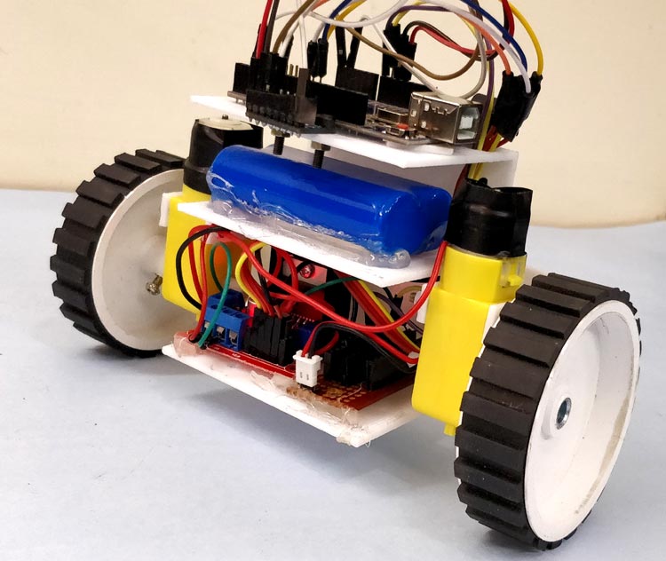
DIY Self Balancing Robot using Arduino
In this tutorial I will document my experience in building the self balancing robot. You might be an absolute beginner who is just getting s...
View project
Sustainable Battery Material For Electric Cars
Researchers have created eco-friendly batteries for EVs, matching cobalt-based batteries in cost-effectiveness with potential for lithium re...
View project
BorgWarner To Integrate STMicroelectronics SiC Technology In Viper Power Module For Volvo Cars Next-Generation EVs
STMicroelectronics will supply BorgWarner Inc. with the latest third generation 750V silicon carbide SiC power MOSFETs dice for their propri...
View project
Longer-Lasting Chips For Smartphones
New chips help users run apps faster, keep devices working longer, and handle more tasks on smartphones, computers, and cars.
View project