

Accelerometer Based Hand Gesture Controlled Robot using Arduino
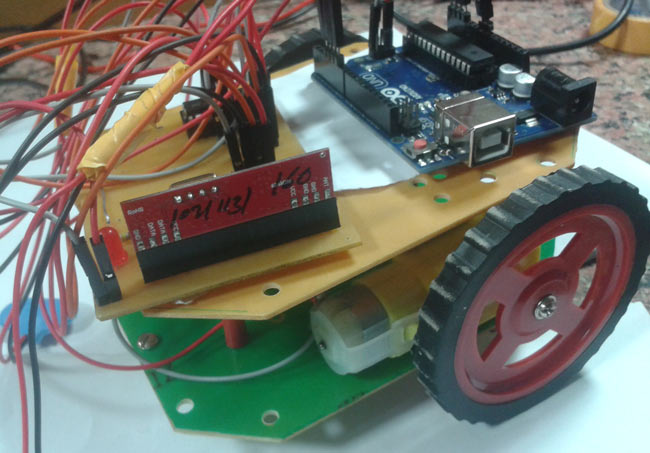
After making some basic robots like line follower robot, computer controlled robot, etc, we have developed this accelerometer based gesture controlled robot by using arduino uno. In this project we have used hand motion to drive the robot. For this purpose we have used accelerometer which works on acceleration.
- Suitable forB.Tech ECE students
- Build time5-7 weeks
- LevelAdvanced
- Available atAjvika Labs, Kakinada
About this project
A gesture controlled robot is controlled by using hand in place of any other method like buttons or joystick. Here one only needs to move hand to control the robot. A transmitting device is used in your hand which contains RF Transmitter and accelero-meter. This will transmit command to robot so that it can do the required task like moving forward, reverse, turning left, turning right and stop. All these tasks will be performed by using hand gesture.
According to the datasheet of adxl335 polysilicon surface-micromachined structure placed on top of silicon wafer. Polysilicon springs suspend the structure over the surface of the wafer and provide a resistance against acceleration forces. Deflection of the structure is measured using a differential capacitor which incorporate independent fixed plates and plates attached to the moving mass. The fixed plates are driven by 180° out-of-phase square waves. Acceleration deflects the moving mass and unbalances the differential capacitor resulting in a sensor output whose amplitude is proportional to acceleration. Phase-sensitive demodulation techniques are then used to determine the magnitude and direction of the acceleration.
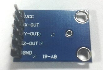
Pin Description of accelerometer
Vcc 5 volt supply should connect at this pin.
X-OUT This pin gives an Analog output in x direction
Y-OUT This pin give an Analog Output in y direction
Z-OUT This pin gives an Analog Output in z direction
ST This pin used for set sensitivity of sensor
Circuit Diagram and Explanation
Gesture Controlled Robot is divided into two sections:
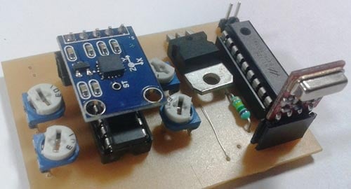
In transmitter part an accelerometer and a RF transmitter unit is used. As we have already discussed that accelerometer gives an analog output so here we need to convert this analog data in to digital. For this purpose we have used 4 channel comparator circuit in place of any ADC. By setting reference voltage we gets a digital signal and then apply this signal to HT12E encoder to encode data or converting it into serial form and then send this data by using RF transmitter into the environment.
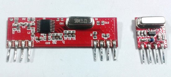
At the receiver end we have used RF receiver to receive data and then applied to HT12D decoder. This decoder IC converts received serial data to parallel and then read by using arduino. According to received data we drive robot by using two DC motor in forward, reverse, left, right and stop direction.
Gesture controlled robot moves according to hand movement as we place transmitter in our hand. When we tilt hand in front side, robot start to moving forward and continues moving forward until next command is given.
When we tilt hand in backward side, robot change its state and start moving in backwards direction until other command is given.
When we tilt it in left side Robot get turn left till next command.
When we tilt hand in right side robot turned to right.
And for stopping robot we keeps hand in stable.
Circuit Diagram for Transmitter Section
Circuit Diagram for Receiver Section
Circuit for this hand gesture controlled robot is quite simple. As shown in above schematic diagrams, a RF pair is used for communication and connected with arduino. Motor driver is connected to arduino to run the robot. Motor driver’s input pin 2, 7, 10 and 15 is connected to arduino digital pin number 6, 5, 4 and 3 respectively. Here we have used two DC motors to drive robot in which one motor is connected at output pin of motor driver 3 and 6 and another motor is connected at 11 and 14. A 9 volt Battery is also used to power the motor driver for driving motors.
In program first of all we have defined output pins for motors.
And then in setup we have given the directions to pin.
After this we read input by using ‘if statement’ and perform relative operation.
There are total five conditions for this Gesture controlled Robot which are giving below:
Input for Arduino from gesture
We have writen the complete program according to the above table conditions. Below is the complete code.
Complete Project Code
Can you please tell me the range of the RF ? I mean for what distance can I use this RF ? Are there ant better ways to transmit the commands ?
can you please tell me which rf pair should i use? Also can i use atmega8 instead of Arduino UNO?
In reply to query regarding components by Jayesh
@Vikram @Jayesh This is ASK RF module Wireless Transmitter & Receiver Pair - 433MHz. It has apporx 100 meter range when operated at max supply voltage (12v). Check its more detail (with images) in this project: RF controlled Robot
In reply to @Vikram @Jayesh This is ASK by Jayant
what is the meaning of temp and fd in programming
I like this project but i dont know how to give program to the robot
In reply to I like this project but i by charankumar
Arduino IDE software (Arduino Nightly : https://www.arduino.cc/en/Main/Software ) is used to write, verify and upload/burn the code into Arduino, through PC
Can we use transmitting ckt with out cmos
In reply to Can we use transmitting ckt by mohanroyal
ilove so much that subjects
What is value of variable resistor set for transmitter circuit?
In reply to What is value of variable by vipin
Please give me PCB layout of this circuit
Hey friend!! Firstly i would like to thank u for uploading this project. I am also making the same project as urs using the same diagram and code and everything but i am not able to successfully run it. Pls help me asap as i hv to submit my project in 3-4 days. I have used same connection and the led on receiver is also glowing but i am not able to figure out the problem as motors r not running.
In reply to don't know where the problem is by shubham
The information is not sufficient, without looking into your code and circuit, we cant help.
In reply to The information is not by Abhishek
Hi Abhishek, This is regarding Accelerometer based hand gesture robot project which u had uploaded in the web. I am unable to get the output. I guess there is a bug in the program. I haave done the same connections and uploaded thr program bit the motors aren't running. I then added baurd rate 9600 into program and added few line of codes but still i am not able ro run the motors. I have used the same hardware components and connectionss which u had done. Below is my source code pls check wat is the bug.
#define FD 16 #define BD 17 #define LD 18 #define RD 19 #define m11 3 #define m12 4 #define m21 5 #define m22 6 void forward() { digitalWrite(m11, HIGH); digitalWrite(m12, LOW); digitalWrite(m21, HIGH); digitalWrite(m22, LOW); } void backward() { digitalWrite(m11, LOW); digitalWrite(m12, HIGH); digitalWrite(m21, LOW); digitalWrite(m22, HIGH); } void left() { digitalWrite(m11, HIGH); digitalWrite(m12, LOW); digitalWrite(m21, LOW); digitalWrite(m22, LOW); } void right() { digitalWrite(m11, LOW); digitalWrite(m12, LOW); digitalWrite(m21, HIGH); digitalWrite(m22, LOW); } void Stop() { digitalWrite(m11, LOW); digitalWrite(m12, LOW); digitalWrite(m21, LOW); digitalWrite(m22, LOW); } void setup() { Serial.begin(9600); pinMode(FD, INPUT); pinMode(BD, INPUT); pinMode(LD, INPUT); pinMode(RD, INPUT); pinMode(m11, OUTPUT); pinMode(m12, OUTPUT); pinMode(m21, OUTPUT); pinMode(m22, OUTPUT); } void loop() { int temp1=digitalRead(FD); int temp2=digitalRead(BD); int temp3=digitalRead(LD); int temp4=digitalRead(RD); Serial.print(analogRead(FD)); Serial.print(\"\t\"); Serial.print(analogRead(BD)); Serial.print(\"\t\"); Serial.print(analogRead(LD)); Serial.print(\"\t\"); Serial.print(analogRead(RD)); Serial.println(); delay(100);
if(temp1==1 && temp2==0 && temp3==0 && temp4==0) backward(); else if(temp1==0 && temp2==1 && temp3==0 && temp4==0) forward(); else if(temp1==0 && temp2==0 && temp3==1 && temp4==0) left(); else if(temp1==0 && temp2==0 && temp3==0 && temp4==1) right(); else Stop(); }
Can I use the same code to drive stepper motors?
In reply to Driving stepper motors by Megashree R
In reply to No, you can't. by Abhishek
Can you please send me a pic of transmitter module?
In reply to No, you can't. by Abhishek
can arduino be used in transmitter instead of receiver in gesture controlled robot ?
I'm new to this rf things...can u explain to me the use of Use of encoder nd decoders
Hello, I built a transmitter module on a bread board and it looks really clumsy because of too many connecting wires and potentiometers. It's too large for a hand palm. However, in the video that you have uploaded, transmitter looks really small. So, kindly upload a picture of the transmitter module alone so that I'll get some idea of optimizing the design.
Should we connect all the components as it is shown in the transmitter and receiver diagrams?
i can not find any accelerometer sensor in proteus.......also encoder-decoder HT12E & HT12D....please help me how to find this component in proteus.......Badly need this component to simulate this project
Technologies used
Hardware components
- Arduino
- Servo Motor
- DC Motor
- L298N
- Ultrasonic Sensor
- ESP32
Software & tools
- Arduino IDE
- ROS
- Python
- OpenCV
- VS Code
Project demo video
What you get
- Working project / hardware kit, tested before delivery
- Complete source code with explanation
- Project demo and guidance for your viva
- Project report, PPT and IEEE paper support (on request)
Related ECE projects
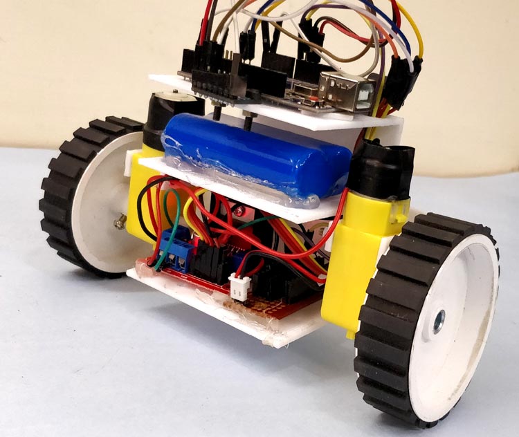
DIY Self Balancing Robot using Arduino
In this tutorial I will document my experience in building the self balancing robot. You might be an absolute beginner who is just getting s...
View project
Sustainable Battery Material For Electric Cars
Researchers have created eco-friendly batteries for EVs, matching cobalt-based batteries in cost-effectiveness with potential for lithium re...
View project
BorgWarner To Integrate STMicroelectronics SiC Technology In Viper Power Module For Volvo Cars Next-Generation EVs
STMicroelectronics will supply BorgWarner Inc. with the latest third generation 750V silicon carbide SiC power MOSFETs dice for their propri...
View project
Longer-Lasting Chips For Smartphones
New chips help users run apps faster, keep devices working longer, and handle more tasks on smartphones, computers, and cars.
View project