


Water Level and Water Quantity Monitoring System using ESP32 using ESP32
In this project, we will build a proper water management tool using esp32. This water management tool will save wasted water by stopping water overflow and also collect daily water usage data of every house.
- Suitable forB.Tech IoT students
- Build time3-4 weeks
- LevelIntermediate
- Available atAjvika Labs, Kakinada
About this project
Proper Management of Water
Limiting the quantity of water supplied to each household depending on the number of members in that household. Monitoring the quantity of water spent by every household every day. Automating the water pump to stop tank overflow (Overhead Tank & Reservoir Tank). By these above 3 key water management strategies I aim to solve the water wastage problem. My device includes all these above-mentioned features and is well capable of preventing water wastage problem which happens due to tank overflow. Implementation: To implement the 3 features that I have previously mentioned in my project I am using a solenoid valve and a water flow meter to Limit the quantity of water supplied to each household. This solenoid valve and water flow meter will be in the inlet of the reservoir tank. When the water flow meter indicates that the required amount of water is supplied to a particular house then the solenoid valve will stop the water flow to the reservoir tank. I am using another water flow meter which will be in the outlet of the overhead tank to monitor the quantity of water spent by every household every day. Now, to automate the water pumps I am using 4 float switches 2 in the reservoir and 2 in the overhead tank to measure the water levels (higher and lower level) of both of these tanks to stop water overflow by starting and stopping the water pump. Let's understand this by an example, suppose a particular house has a water storage capacity of 500Lts(250Lts. Reservoir+ 250Lts overhead tank)., but the water supplied to the house is 700Lts. Now, when the reservoir is full the water pump will start and the overhead tank will start filling up, and when the overhead is also full then the solenoid valve will stop the water flow to the reservoir tank. Higher and Lower levels of water will be detected by float switches. Now the extra 200Lts. of water is saved by that user which will reflect in the Mobile Application. All these measurements and automation of the pump will be controlled by a single microcontroller which is ESP32. This ESP32 will send the water usage data to the cloud database through the internet. A user (house) will have a Mobile Application where he/she can monitor the daily water usage and water saved by them. A user also can apply for extra water for any occasion in his/her house through this mobile app. As this system creates a network and a database of water usage data, That's why I call it Water NET.
Before proceeding, please review our previously constructed water monitoring system related projects,
Raspberry Pi Hot Water Tank Leak Detector using SPI Modules
Smart Water Quality Monitoring System Using IoT
Sewage Monitoring and Maintenance Alert using IoT
An Automatic Wireless Water Pump Controller
Component Required for Water Net
Project Used Hardware
ESP 32 (Wroom32), Water Flow Sensor (SAIER-> HZ21WA), Float Switch, Sugar cube Relay (JIH JIK-> JQC-3FC(T73)DC12V), Power Relay (Elecfuture-> EF93-12), Relay Jack, Transistor (BC547), LM7805, Red LED (5 m.m.), Green LED (5 m.m.), Blue LED (5 m.m.), Common cathode RGB LED (5 m.m.), 5 m.m. LED holder, THT Resistor (100 ohm/ 0.25 watt), Solenoid Valve (1/2 inch, 230volt), SMPS socket & Jack, Speaker terminal connector, Cable gland (PG7), 16 Amp AC socket, Relimate connectors, Push Switches, Heat Shrink Tubes (2.5 m.m., 6 m.m.), Vero Board (Dotted), PVC box (10” x 8”), 230/12 volt, 500mA Transformer, Diode 1N4007, Electrolytic Capacitors (1000uF, 25 volt), Nut bolts, 1.5 Sq. m.m. 3 Core Cable with plug, 1.5 inch PVC Endcap
Project Used Software
Project Hardware/Software Selection
As an enclosure of this system, I have used a 10” x 8” PVC box. I used a dotted Vero board to solder all the components except the relay. Because the relay is not vero friendly, so I stick the relays with some tissue tape. A relay jack is used to power up the relay which will drive the water pump and the sugar cube relay will drive the solenoid valve. For connecting the solenoid valve to the box I have used an SMPS socket and jack on the right side of the box. ESP32 is the core controller of the whole system. I have chosen this board over NodeMCU because it has more GPIOs and processing power which I can use later on for more improvement. There are two (2) push switches to manually operate the water pump in case of any emergency. LED holder is used to hold all the LEDs on the top panel. For connecting the wire of the float switches & flow sensors I have used two (2) speaker terminals on the left side of the box. All the connectors, relay, and LEDs are connected to the circuit using relimate connectors. In this circuit, some resistors are used for the current limiting purpose of the transistor base and LEDs. Some diodes are also used for the relay and the bridge rectifier. For powering up the whole system a 230/12-volt step-down transformer is used with a bridge rectifier, filter, and some voltage regulators. 230 volt, 50 Hz A.C. is provided to the system through a 1.5 sq. m.m. 3 core cable. I used a cable gland PG7 for putting the cable inside of the box. A 16 amps 3pin socket is present to connect the water pump to the box. ESP32 is capable of connecting to the internet through wifi. But getting the wifi in every household is not possible, so I used an LTE router that has a sim card in it and provides a hotspot network. I soldered some wire from the LTE router ‘ Network indication LED ’ and connect it to an RGB LED which is mounted on the top panel. LED indicators: Power LED – RED Network LED – RGB Pump Status – GREEN Reservoir Status – BLUE
Water Net Circuit Diagram
The water flow sensors are supplied with a 3.3 volt supply. The pulse/ output pin of the first flow sensor is connected to pin D12 and the second flow sensor's pulse/ output pin is connected to pin D13 of the ESP32. The float switch has 4 wires one is connected to Gnd and another is connected to a digital pin. All the digital pin connected to the float switches is internally pulled up. 4 float switches are connected to pin D15, D18, D1 & D21 of ESP32. Relays are driven by the ESP32 with the help of BC547 transistors. To limit the base current of the transistors 100-ohm resistor is used. Solenoid relays transistor base pin is connected to D22 & water pump relays transistor base pin is connected to D23. The reservoir empty led is connected to the D4 pin of the ESP32. 7805 regulates the voltage to 5 volts for supplying the ESP32.
The application of this system is obvious, saving the wasted water by stopping the water overflow. The problem of water shortage is not only the problem of India anymore, it is also the problem of our world. As this system will not only stop the water overflow it will also collect the daily water usage data of every house. This data will help policymakers and the water supply board to make necessary and important decisions regarding the water supply. Govt. bodies can use this system to manage water supply properly and start saving water. A single homeowner can also use this system to automate their responsibility of saving water.
Complete Project Code
Technologies used
Hardware components
- ESP32
- ESP8266
- Arduino
- DHT22
- Relay
- OLED
- NodeMCU
Software & tools
- Arduino IDE
- Blynk
- Firebase Console
- Node-RED
- MQTT Broker
What you get
- Working project / hardware kit, tested before delivery
- Complete source code with explanation
- Project demo and guidance for your viva
- Project report, PPT and IEEE paper support (on request)
Related IoT projects

DIY IoT Plant Watering System using Arduino
A remote plant-watering system that monitors soil moisture and lets you trigger a water pump from anywhere through the Blynk app, with LED-m...
View project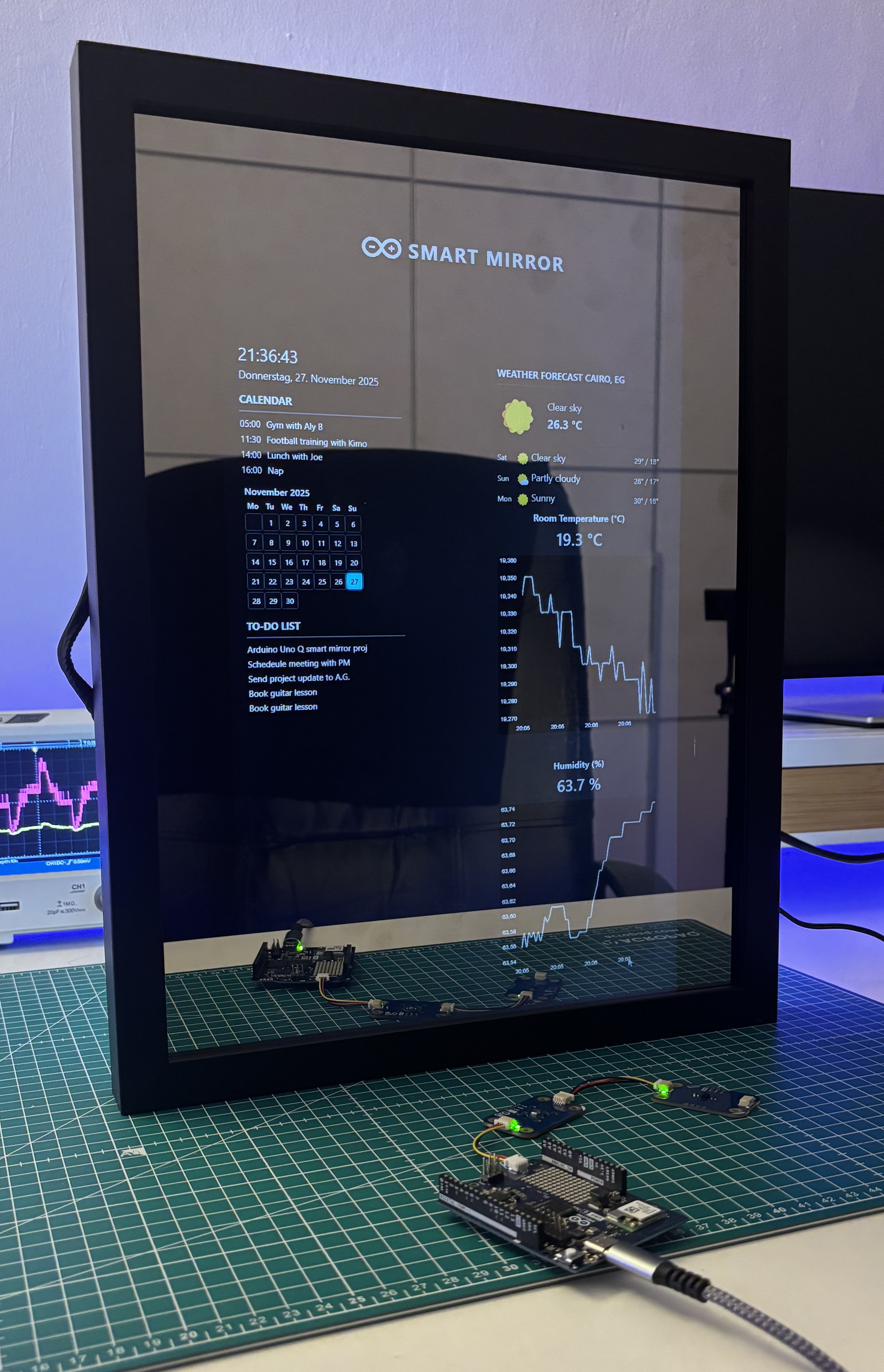
Build a smart mirror with an Arduino UNO Q
A wall-mounted smart mirror that shows the time, calendar, to-do list, room temperature/humidity and weather forecast behind a two-way glass...
View project
ESP32 Patient Health Monitor ECG SpO2 BPM Live Dashboard
Build a complete patient health monitoring system using ESP32 with AD8232 ECG sensor, MAX30102 pulse oximeter, BME280 and live web dashboard...
View project
IoT AC Energy Meter with PZEM-004T and ESP32 WebServer
Build an IoT-based AC energy meter using ESP32 and PZEM-004T to measure voltage, current, power, frequency and energy with live web dashboar...
View project