Solar-Powered Vital Monitoring for Traffic Police & Outdoor Workers MAXREFDES117 Bio-Sensor from Analog Devices
Solar-powered wearable using Analog Devices MAXREFDES117 and ESP32 for real-time heart rate & SpO2 monitoring with heat stress alerts for outdoor workers.
- Suitable forB.Tech IoT students
- Build time3-4 weeks
- LevelIntermediate
- Available atAjvika Labs, Kakinada
About this project
By Ann Theressa Babu
This project presents a prototype of a solar-powered wearable vital monitoring system designed to support individuals who work for long hours in outdoor and physically demanding environments. The system uses the Analog Devices MAXREFDES117 optical heart-rate module to measure heart rate and blood-oxygen saturation using photoplethysmography (PPG) signals.
An ESP32 microcontroller processes the physiological signals and displays real-time vital parameters on a compact OLED display. The measured heart rate and SpO2 values are analyzed to identify patterns associated with physiological strain, enabling the system to flag conditions such as fatigue, dehydration risk, and heat stress. Audible alerts are generated when abnormal physiological conditions are detected, providing immediate feedback to the user in addition to visual indicators. An audible indication is also used to signal improper sensor placement, helping maintain measurement reliability during operation.
The device is designed with a solar-assisted power architecture, in which a small solar panel is used to recharge a lithium-ion battery through a dedicated TP4056 charging module, enabling extended operation with minimal dependence on manual charging. This power approach supports the concept of continuous monitoring during long outdoor work shifts.
Traffic police, construction laborers, delivery riders, municipal staff, and street vendors often work in harsh environments with high heat, pollution, and long hours, yet their health is rarely monitored. Recent incidents – such as the Kerala police commissioner who collapsed during a Republic Day parade due to heat-related strain – highlight how prolonged hours of outdoor activity are vulnerable to sudden fatigue and physiological stress. This project demonstrates a low-cost, wearable health-monitoring concept that can provide early warning of physiological strain and encourage timely rest or intervention, thereby improving safety and wellbeing for essential frontline workers.
The circuit diagram of the project, made with EasyEDA, is attached here.
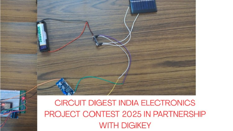
1. Connect the battery to the charging module: The 3.7 V lithium-ion battery is connected to the TP4056 charging module by wiring the battery positive terminal to BAT+ and the negative terminal to BAT−. This battery acts as the power source for the system.
2. Attach the solar panel for charging: The output terminals of the solar panel are connected to the IN+ and IN− pins of the TP4056 module. This allows the battery to be charged using solar energy when sunlight is available.
3. Link the charging module to the boost converter: The output of the TP4056 module is connected to the input of the DC-DC boost converter (XL6009E1). This step passes the battery voltage to the voltage regulation stage.
4. Set the boost converter output voltage: Using a multimeter in DC voltage mode, the output of the boost converter is measured and adjusted to approximately 5V by rotating the onboard adjustment screw. This adjustment is completed before connecting the ESP32 to prevent damage.
5. Power the ESP32 development board: The regulated 5 V output from the boost converter is connected to the VIN pin of the ESP32 DevKit V1, and the ground is connected to the ESP32 ground pin, supplying power to the microcontroller.
6. Connect the biosensor module: The Analog Devices MAXREFDES117 biosensor module is connected to the ESP32 using the I2C interface. The SDA and SCL lines are connected to GPIO21 and GPIO22, respectively, while power is supplied from the ESP32’s 3.3 V and GND pins.
7. Connect the OLED display: The OLED display module is connected to the same I2C lines as the biosensor. Its SDA and SCL pins are connected to the ESP32, and it is powered using 3.3 V and GND from the ESP32.
8. Add alert and indication components: An active piezo buzzer is connected to GPIO15 pin on the ESP32. It provides audible feedback during system operation.
9. Assemble the prototype structure
10 .Check connections and power on the system
The firmware for the system is developed using the Arduino IDE and runs on the ESP32 microcontroller. The code integrates three main functional blocks: sensor data acquisition, physiological condition analysis, and user feedback through display and alerts.
Required Software Libraries
The following open-source libraries are used to support sensor communication, signal processing, and display control:
SparkFun MAX3010x Sensor Library Used to interface with the MAXREFDES117 optical biosensor and acquire PPG data from the red and infrared LEDs.
SparkFun MAX3010x Sensor Library
Used to interface with the MAXREFDES117 optical biosensor and acquire PPG data from the red and infrared LEDs.
HeartRate Library Provides peak-detection functionality to estimate heart rate from the PPG waveform.
Provides peak-detection functionality to estimate heart rate from the PPG waveform.
Adafruit SSD1306 Library Used to control the 128×64 OLED display and render text and graphics.
Adafruit SSD1306 Library
Used to control the 128×64 OLED display and render text and graphics.
Adafruit GFX Library A core graphics library required by the SSD1306 driver for text formatting and display rendering.
Adafruit GFX Library
A core graphics library required by the SSD1306 driver for text formatting and display rendering.
Adafruit BusIO Library Handles low-level I2C communication required by the display library.
Adafruit BusIO Library
Handles low-level I2C communication required by the display library.
Wire Library The built-in Arduino I2C library used for communication between the ESP32, biosensor, and OLED display.
The built-in Arduino I2C library used for communication between the ESP32, biosensor, and OLED display.
The MAXREFDES117 optical biosensor communicates with the ESP32 using the I2C protocol. Infrared (IR) and red light PPG signals are continuously read from the sensor. The IR signal is primarily used to detect the presence of valid physiological data, while both IR and red signals are used to estimate heart rate and blood oxygen saturation (SpO₂). A basic validity check is applied to the IR signal. If the signal strength is below a defined threshold, the system assumes that no reliable measurement is available and displays a neutral message (“No data available”) instead of reporting incorrect values.
Heart rate is calculated by detecting peaks in the PPG waveform using a beat-detection algorithm. The time interval between successive beats is converted into beats per minute (BPM). Unrealistic values are discarded to improve stability. SpO₂ is estimated using the ratio of red and infrared signal intensities. The calculated value is constrained within a realistic physiological range to reduce the effect of noise and motion artifacts.
The measured heart rate and SpO₂ values are analyzed to identify patterns associated with physiological strain. Based on predefined ranges, the system classifies the user’s condition into categories such as:
This classification is intended to flag potential risk conditions rather than provide medical diagnosis.
An SSD1306-based OLED display is used to show real-time heart rate, SpO₂, and the current physiological status. The display is updated periodically to provide clear and readable information. An active piezo buzzer is controlled by a GPIO pin on the ESP32. The buzzer generates a short audible alert only when abnormal physiological conditions are detected. No audible alert is produced when sensor data is unavailable, preventing unnecessary or misleading alarms.
Real-time vital monitoring
Continuous measurement of heart rate and blood oxygen saturation using PPG sensing.
Physiological stress indication
Identification of patterns associated with fatigue, dehydration risk, heat stress, and circulatory stress.
Clear visual feedback
OLED-based display of vital parameters and system status.
Context-aware audible alerts
Audible alerts generated only during abnormal physiological conditions.
Reliable data handling
Validation of sensor data to avoid displaying incorrect readings.
Low-power wearable concept
Designed for battery-based, solar-assisted operation in outdoor environments.
Expandable software architecture
Supports future integration of wireless communication, web dashboards, and machine-learning-based analysis.
Complete Project Code
This project presents a prototype of a solar-powered wearable vital monitoring system designed to support individuals who work for long hours in outdoor and physically demanding environments. The system uses the Analog Devices MAXREFDES117 optical heart-rate module to measure heart rate and blood-oxygen saturation using photoplethysmography (PPG) signals.
An ESP32 microcontroller processes the physiological signals and displays real-time vital parameters on a compact OLED display. The measured heart rate and SpO2 values are analyzed to identify patterns associated with physiological strain, enabling the system to flag conditions such as fatigue, dehydration risk, and heat stress. Audible alerts are generated when abnormal physiological conditions are detected, providing immediate feedback to the user in addition to visual indicators. An audible indication is also used to signal improper sensor placement, helping maintain measurement reliability during operation.
The device is designed with a solar-assisted power architecture, in which a small solar panel is used to recharge a lithium-ion battery through a dedicated TP4056 charging module, enabling extended operation with minimal dependence on manual charging. This power approach supports the concept of continuous monitoring during long outdoor work shifts.
Traffic police, construction laborers, delivery riders, municipal staff, and street vendors often work in harsh environments with high heat, pollution, and long hours, yet their health is rarely monitored. Recent incidents – such as the Kerala police commissioner who collapsed during a Republic Day parade due to heat-related strain – highlight how prolonged hours of outdoor activity are vulnerable to sudden fatigue and physiological stress. This project demonstrates a low-cost, wearable health-monitoring concept that can provide early warning of physiological strain and encourage timely rest or intervention, thereby improving safety and wellbeing for essential frontline workers.
The circuit diagram of the project, made with EasyEDA, is attached here.
1. Connect the battery to the charging module: The 3.7 V lithium-ion battery is connected to the TP4056 charging module by wiring the battery positive terminal to BAT+ and the negative terminal to BAT−. This battery acts as the power source for the system.
2. Attach the solar panel for charging: The output terminals of the solar panel are connected to the IN+ and IN− pins of the TP4056 module. This allows the battery to be charged using solar energy when sunlight is available.
3. Link the charging module to the boost converter: The output of the TP4056 module is connected to the input of the DC-DC boost converter (XL6009E1). This step passes the battery voltage to the voltage regulation stage.
4. Set the boost converter output voltage: Using a multimeter in DC voltage mode, the output of the boost converter is measured and adjusted to approximately 5V by rotating the onboard adjustment screw. This adjustment is completed before connecting the ESP32 to prevent damage.
5. Power the ESP32 development board: The regulated 5 V output from the boost converter is connected to the VIN pin of the ESP32 DevKit V1, and the ground is connected to the ESP32 ground pin, supplying power to the microcontroller.
6. Connect the biosensor module: The Analog Devices MAXREFDES117 biosensor module is connected to the ESP32 using the I2C interface. The SDA and SCL lines are connected to GPIO21 and GPIO22, respectively, while power is supplied from the ESP32’s 3.3 V and GND pins.
7. Connect the OLED display: The OLED display module is connected to the same I2C lines as the biosensor. Its SDA and SCL pins are connected to the ESP32, and it is powered using 3.3 V and GND from the ESP32.
8. Add alert and indication components: An active piezo buzzer is connected to GPIO15 pin on the ESP32. It provides audible feedback during system operation.
9. Assemble the prototype structure
10 .Check connections and power on the system
The firmware for the system is developed using the Arduino IDE and runs on the ESP32 microcontroller. The code integrates three main functional blocks: sensor data acquisition, physiological condition analysis, and user feedback through display and alerts.
Required Software Libraries
The following open-source libraries are used to support sensor communication, signal processing, and display control:
SparkFun MAX3010x Sensor Library Used to interface with the MAXREFDES117 optical biosensor and acquire PPG data from the red and infrared LEDs.
SparkFun MAX3010x Sensor Library
Used to interface with the MAXREFDES117 optical biosensor and acquire PPG data from the red and infrared LEDs.
HeartRate Library Provides peak-detection functionality to estimate heart rate from the PPG waveform.
Provides peak-detection functionality to estimate heart rate from the PPG waveform.
Adafruit SSD1306 Library Used to control the 128×64 OLED display and render text and graphics.
Adafruit SSD1306 Library
Used to control the 128×64 OLED display and render text and graphics.
Adafruit GFX Library A core graphics library required by the SSD1306 driver for text formatting and display rendering.
Adafruit GFX Library
A core graphics library required by the SSD1306 driver for text formatting and display rendering.
Adafruit BusIO Library Handles low-level I2C communication required by the display library.
Adafruit BusIO Library
Handles low-level I2C communication required by the display library.
Wire Library The built-in Arduino I2C library used for communication between the ESP32, biosensor, and OLED display.
The built-in Arduino I2C library used for communication between the ESP32, biosensor, and OLED display.
The MAXREFDES117 optical biosensor communicates with the ESP32 using the I2C protocol. Infrared (IR) and red light PPG signals are continuously read from the sensor. The IR signal is primarily used to detect the presence of valid physiological data, while both IR and red signals are used to estimate heart rate and blood oxygen saturation (SpO₂). A basic validity check is applied to the IR signal. If the signal strength is below a defined threshold, the system assumes that no reliable measurement is available and displays a neutral message (“No data available”) instead of reporting incorrect values.
Heart rate is calculated by detecting peaks in the PPG waveform using a beat-detection algorithm. The time interval between successive beats is converted into beats per minute (BPM). Unrealistic values are discarded to improve stability. SpO₂ is estimated using the ratio of red and infrared signal intensities. The calculated value is constrained within a realistic physiological range to reduce the effect of noise and motion artifacts.
The measured heart rate and SpO₂ values are analyzed to identify patterns associated with physiological strain. Based on predefined ranges, the system classifies the user’s condition into categories such as:
This classification is intended to flag potential risk conditions rather than provide medical diagnosis.
An SSD1306-based OLED display is used to show real-time heart rate, SpO₂, and the current physiological status. The display is updated periodically to provide clear and readable information. An active piezo buzzer is controlled by a GPIO pin on the ESP32. The buzzer generates a short audible alert only when abnormal physiological conditions are detected. No audible alert is produced when sensor data is unavailable, preventing unnecessary or misleading alarms.
Real-time vital monitoring
Continuous measurement of heart rate and blood oxygen saturation using PPG sensing.
Physiological stress indication
Identification of patterns associated with fatigue, dehydration risk, heat stress, and circulatory stress.
Clear visual feedback
OLED-based display of vital parameters and system status.
Context-aware audible alerts
Audible alerts generated only during abnormal physiological conditions.
Reliable data handling
Validation of sensor data to avoid displaying incorrect readings.
Low-power wearable concept
Designed for battery-based, solar-assisted operation in outdoor environments.
Expandable software architecture
Supports future integration of wireless communication, web dashboards, and machine-learning-based analysis.
Complete Project Code
Technologies used
Hardware components
- ESP32
- ESP8266
- Arduino
- DHT22
- Relay
- OLED
- NodeMCU
Software & tools
- Arduino IDE
- Blynk
- Firebase Console
- Node-RED
- MQTT Broker
Project demo video
What you get
- Working project / hardware kit, tested before delivery
- Complete source code with explanation
- Project demo and guidance for your viva
- Project report, PPT and IEEE paper support (on request)
Delivery & Payment
Delivery takes a minimum of two weeks from the date your inquiry is confirmed.
Payment is in two parts:
• 50% advance to start the project
• Remaining 50% before delivery
Note:
• Documentation and PPT are not included by default
• If you need documentation/PPT, it can be arranged for extra time and cost
We'll confirm the exact timeline and cost with you after reviewing your requirements.
Related IoT projects

IoT
DIY IoT Plant Watering System using Arduino
A remote plant-watering system that monitors soil moisture and lets you trigger a water pump from anywhere through the Blynk app, with LED-m...
View project
IoT
Build a smart mirror with an Arduino UNO Q
A wall-mounted smart mirror that shows the time, calendar, to-do list, room temperature/humidity and weather forecast behind a two-way glass...
View project
IoT
ESP32 Patient Health Monitor ECG SpO2 BPM Live Dashboard
Build a complete patient health monitoring system using ESP32 with AD8232 ECG sensor, MAX30102 pulse oximeter, BME280 and live web dashboard...
View project
IoT
IoT AC Energy Meter with PZEM-004T and ESP32 WebServer
Build an IoT-based AC energy meter using ESP32 and PZEM-004T to measure voltage, current, power, frequency and energy with live web dashboar...
View project