Smart Video Doorbell using ESP32 Cam
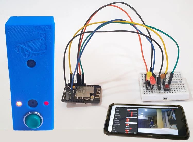
This Smart Wi-Fi Video Doorbell using ESP32-CAM can be powered by an AC socket and whenever someone at the door presses the doorbell button, it will play a specific song on your phone and sends a text message with a link of video streaming page where you can see the person at the door from anywhere in world.
- Suitable forB.Tech IoT students
- Build time3-4 weeks
- LevelIntermediate
- Available atAjvika Labs, Kakinada
About this project
In another tutorial, we have learned about ESP32-CAM and how to use it for video streaming, now we will make a Smart Wi-Fi Video Doorbell using ESP32-CAM. This Smart doorbell can easily be powered by an AC socket and whenever someone at the door presses the doorbell button, it will play a specific song on your phone and sends a text message with a link of video streaming page where you can see the person at the door from anywhere in world.
FTDI Programming Board
220V AC to 5V DC Converter
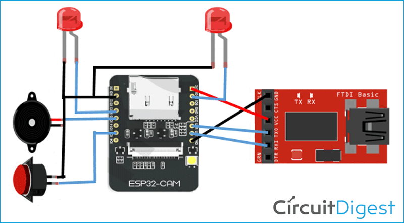
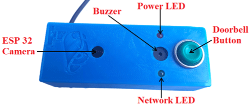
Circuit diagram for this Smart Wi-Fi Doorbell is very simple, just connect two LEDs, a push button and a buzzer to ESP32 GPIO pins. A buzzer is used to make a sound whenever the button is pressed. One LED is used to indicate the power status, and the other LED is used to indicate the network status. Network LED will be in a high state if ESP is connected to a network otherwise, it will blink.
This is how the Wi-Fi video doorbell setup will look in 3D printed casing:
IFTTT Setup for Wi-Fi Doorbell
IFTTT is a free web-based service that allows users to create chains of simple conditional statements, called “recipes”, which are triggered based on changes to other web services such as Gmail, Facebook, Instagram, and Pinterest. IFTTT is an abbreviation of “If This Then That”.
In this project, IFTTT is used to send an Email whenever the temperature or humidity goes beyond a predefined limit. We previously used IFTTT in many IoT based projects to send emails or SMS on particular events like on excessive electricity consumption, on high pulse rate, on intruder entry, etc.
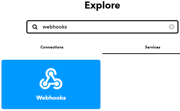
Now search for ‘Webhooks’ and click on the Webhooks in Services section.
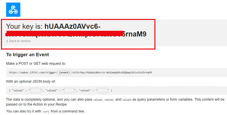
Now, in the Webhooks window, click on ‘Documentation’ in the upper right corner to get the private key.
Copy this key. It will be used in the program.
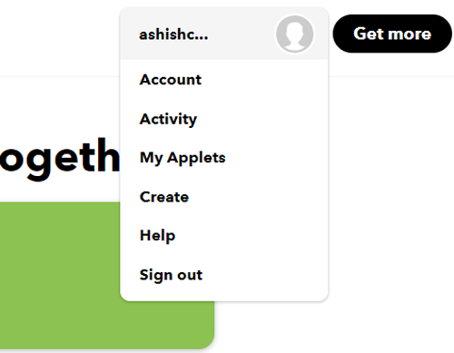
After getting the private key, now we will create an applet using Webhooks and Email services. To create an applet click on your profile and then click on ‘ Create. ’
Now in the next window, click on the ‘This’ icon.
Now search for Webhooks in the search section and click on ‘ Webhooks. ’
Now choose ‘ Receive a Web Request’ trigger and in the next window, enter the event name as button_pressed and then click on create a trigger.
Now to complete the applet, click on ‘That’ to create a reaction for the button_pressed event.
Here we will play a specific song on the phone when the IoT doorbell button is pressed. For that search for ‘Android device’ in the search section.
Now in Android Device, choose ‘ Play a specific song’ trigger.
Now enter the song title that you want to play when the doorbell button is pressed. In my case, I’m playing a song named ‘123’ from my Google play music. You can also use Spotify or other music apps.
After that, click on ‘ Create action’ and then ‘Finish’ to complete the process.
Now create another applet to send a message with the webpage link to the phone when the doorbell button is pressed.
So to create this applet choose ‘ Webhooks ’ in ‘ this ’ section and in ‘that’ section choose ‘ Android SMS .’
Now it will ask to enter the phone number and message body. For this Wi-Fi doorbell project, we are sending a message with the Webserver link so that you can see the live video streaming directly.
Complete code along with the video for this Wi-Fi doorbell camera is given at the end of this document. It can also be downloaded from here. Below we are explaining some important parts of the code.
First, include all the required library files for this code.
Then enter the Wi-Fi credentials.
After that, enter the IFTTT hostname and private key that you copied from the IFTTT website.
Define all the pins that you are using in this project. I’m using the GPIO 2, 14 and 15 pins to connect the push button, LED and buzzer.
Inside the void setup loop, define the button pin as input and LED and buzzer pins as output.
It will try to connect to Wi-Fi using the given credentials, and when connected to a network LED state will change from low to high.
While disconnected from a network ESP32 will restart until it connects to a network.
ESP32 will read the button state, and if the button is in the LOW state (pulled high), i.e., a button has been pressed, it sends the event and turns on the buzzer for 3 seconds.
3D Printed Casing for Smart Wi-Fi Doorbell
Here I designed a 3D printed casing for this wireless doorbell camera. For that, I measured the dimensions of the ESP32 board, Pushbutton, Buzzer and LED using my vernier caliper and the design looked something like this below once it was done.
After that, I exported it as an STL file, sliced it based on printer settings, and finally printed it. The STL file is available for download from Thingiverse and you can print your own casing using it.
After printing the case, I assembled the circuit into my casing and everything was a nice fit, as you can see here.
If you want to know more about a 3D printer and how it works you can read this article on Beginners Guide to Getting Started with 3D Printing and can also check our other projects where we used 3D printed casings like Biped Robot, Robotic Arm, etc.
Testing the Smart Wi-Fi Doorbell
After assembling the circuit, power the Doorbell using an AC socket. Now whenever the IoT doorbell button is pressed the smartphone starts playing a song named ‘123,’ and a message will be received with a link of a webpage as shown below, where the live video feed can be seen.
Complete code and working video for this Smart Wi-Fi doorbell can be found at the end of the document or you can download the code from here. If you have any queries regarding this project, leave them in the comment section.
Complete Project Code
Dear Circuit Digest Team
This is P.KANAKARAJA Assistant Professor KL University
Your project Implimentation and explinations and code explinations are very very good when compared to the other Domains like instructables, Hotstar, Hackday and adafruit projects i like very much sir thank you for providing such a higher end projects with clear explinations most important thing is you are providing Open source that is the good thing i am very much like this open source environment for the sake of spreading huge knowledge to the society thanks a lot dear \"CIRCUIT DIGEST\"
In reply to GOOD ONE SIR by PAMARTHI KANAKARAJA
I need complete circuit diagram with power supply for this project.
In reply to GOOD ONE SIR by PAMARTHI KANAKARAJA
I can't get link in msg, just the message is received, also network led is not high?
What's the problem, plzz reply
Dear Circuit Digest Team, plese let me know what is the procedure to publish the Project in your web site i am also very intresting to share my knowledge to the socity through your web site kindly tel me sir how it is publish in website
In reply to HOW CAN I PUBLISH PROJECT by PAMARTHI KANAKARAJA
You can mail your project ideas to [email protected]
what software are you using to see the video? It seems to be able to change some of the video paramenters
Hi, very nice project.
Could you send better picture how you conect everything together?
I am not the best from electronic.
can you send the circuit connection clearly
Hi, this project could be done with an ESP-32 (non camera) and an OV7670 camera module?
Thanks to the author, I made the project and the combination has been completed. I also modified the 3D shell, which can be hung on the wall. At present, I put it next to the door of my company. When I leave, the express delivery, he presses the button ESP32 and the smart camera Wi-Fi Video Doorbell Automatically Sends IFTTT Message to My Phone and I'll Rush Back to Work (The following is a schematic diagram of my actual assembly steps:) (I modified all and drew a new picture to create a 3D base ESP32 CAM fixed into the base (without hot melt glue), it has been converted into STL format, and can be printed on a 3D printer. If you want, I can share it with you, leave a message your email@)
Technologies used
Hardware components
- ESP32
- ESP8266
- Arduino
- DHT22
- Relay
- OLED
- NodeMCU
Software & tools
- Arduino IDE
- Blynk
- Firebase Console
- Node-RED
- MQTT Broker
Project demo video
What you get
- Working project / hardware kit, tested before delivery
- Complete source code with explanation
- Project demo and guidance for your viva
- Project report, PPT and IEEE paper support (on request)
Related IoT projects

DIY IoT Plant Watering System using Arduino
A remote plant-watering system that monitors soil moisture and lets you trigger a water pump from anywhere through the Blynk app, with LED-m...
View project
Build a smart mirror with an Arduino UNO Q
A wall-mounted smart mirror that shows the time, calendar, to-do list, room temperature/humidity and weather forecast behind a two-way glass...
View project
ESP32 Patient Health Monitor ECG SpO2 BPM Live Dashboard
Build a complete patient health monitoring system using ESP32 with AD8232 ECG sensor, MAX30102 pulse oximeter, BME280 and live web dashboard...
View project
IoT AC Energy Meter with PZEM-004T and ESP32 WebServer
Build an IoT-based AC energy meter using ESP32 and PZEM-004T to measure voltage, current, power, frequency and energy with live web dashboar...
View project