


Let's Build a Low Cost Drone using ESP32
Learn how to build a WiFi-controlled drone using ESP32 modules and MPU6050 IMU. This DIY project offers stability control, smartphone control, and easy upgradability. Get step-by-step instructions and a complete circuit diagram.
- Suitable forB.Tech IoT students
- Build time3-4 weeks
- LevelIntermediate
- Available atAjvika Labs, Kakinada
About this project
DIY ESP32 Drone Flight Controller - Quick Overview
Build Time: 6-8 hours | Cost: $30-50 | Difficulty: Intermediate
What You'll Learn: ESP32 firmware flashing, MPU6050 IMU integration, PWM motor control, WiFi smartphone connectivity
Applications: Indoor flying practice, Educational drone prototyping, Sensor upgrades for position hold, Basic aerial photography
Update: This ESP32 drone project has now evolved and is called LiteWing - ESP32-based programmable Drone. We have improved the design and functionality, you can now program and control the drone not just from the ESP-Drone mobile application, but also cfclient and cflib Python API. The complete ESP32 drone GitHub repository now includes advanced features like height hold, position hold. This means you can program your ESP32 drone using Python and implement more features like height hold, position hold, gesture control, etc.
This DIY drone is small in size and can be built using easily available components such as ESP32 modules, MPU6050 IMU, coreless motors, and plastic propellers. Check out our collection of drone projects designed for makers and hobbyists.
ESP32 Drone vs Commercial Drone
PCB Design and Layout
Motor Rotation & Propeller Direction Configuration
Three Methods to Flash ESP32 Drone Firmware
└ ⇒ Method 1: Building from Source using ESPIDF
└ ⇒ Method 2: Using ESPTOOL
└ ⇒ Method 3: Using ESP32 Flash Download Tool
Key Features of This ESP32 Drone Flight Controller
This ESP32 drone project incorporates professional-grade features typically found in commercial flight controllers, making it an excellent learning platform and functional quadcopter for indoor flying.
» WiFi controlled: The Drone using ESP32 can be controlled using a smartphone.
» MPU6050 IMU for stability control.
» All-in-one PCB: Doesn’t need any 3D printed parts or such.
» Easily upgradable: Additional features such as position hold or height hold can be added using external modules.
» Small size and lightweight.
» Built-in battery charger.
» Built-in USB interface for programming and debugging. » Android and IOS apps.
ESP32 Drone vs Commercial Drone Controller Comparison
Components Required to Build the ESP32 Drone Flight Controller
The components required to build the DIY WiFi-controlled drone are listed below. The exact value of each component can be found in the schematics or the BOM. Building this ESP32 drone project requires specific electronic components, each playing a critical role in flight control, power management, and wireless communication.
ESP32 Wroom Module – x1
CP2102N USB - UART controller – x1
TP4056 Li-ion charger IC – x1
MIC5219-3.3YM5 3.3v LDO – x1
AO3401 P - MOSFET – x1
2N7002DW dual N-MOSFET – x1
SI2302 N - MOSFET – x4
Type C USB Connector 16Pin – x1
LiPo Battery 1300mAh 30C – x1
720 Coreless Motor – x4
55mm propeller type A(CW) – x2
55mm propeller type B(CCW) – x2
7mm rubber grommet – x4
SMD resistors and capacitors
3D printed Enclosure and mounting screws
Other tools and consumables.
Complete ESP32 Drone Build Cost Breakdown
Here is the approximate cost of building the drone. Please note that the costs provided here are approximate and may vary depending on the vendor. The prices are calculated based on the cheapest options available from reputed vendors, with only the bare minimum number of components as the minimum MOQ. One of the major advantages of this ESP32 drone project is its affordability.
ESP32 Drone Circuit Diagram - Complete Schematics
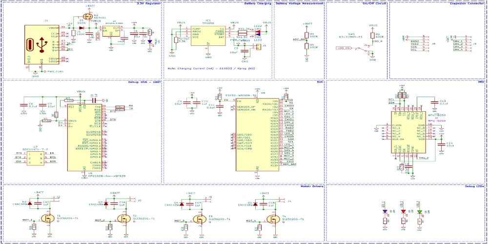
The complete ESP32 drone circuit diagram for the DIY WiFi Controlled Drone is shown below. It can also be downloaded in PDF format from the link given at the end. The circuit design for this ESP32 drone flight controller integrates multiple subsystems, including power management, motor control, sensor interface, and wireless communication.
Let’s discuss the Schematics section by section for better understanding. A type C USB port is used for both charging as well as programming purposes. The power from the USB port is connected to a power path controller circuit built around a P-Channel MOSFET U2 and a diode D1. When the USB power is available, the device will operate from the USB power and will also charge the internal battery. When the USB power is cut, the device will automatically change to battery power. For voltage regulation, we have used a MIC5219 3.3V LDO from Microchip, which is capable of providing up to 500mA of current with a very low dropout voltage of 500mV at full load. A slide switch with a pull-up resistor is connected to the enable pin of MIC5219. This switch is used for turning on and off the thermal camera. When this pin is pulled to the ground, the LDO will be shut down, and hence the other parts of the device too, except the battery charging section. For charging the internal battery, we are using a TP4056 charge controller, which is capable of a maximum charge current of 1A. For battery voltage sensing, we have used a classic voltage divider, which will reduce the battery voltage to a safe level for measurement.
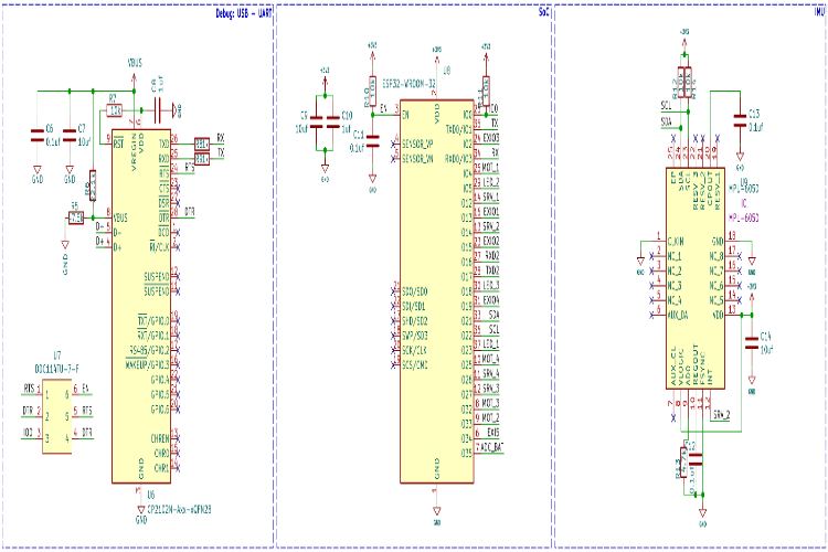
In the next section, we have the ESP32 SoC itself, along with the programming circuit and the MPU6050 PMU chip. The programming circuit consists of a CP2102 USB to UART controller along with a 2N7002DW dual N – N-N-Channel MOSFET from ON Semi. We have used the CP2102 with the QFN28 package. The tiny dual MOSFET will act as an auto-reset circuit for the ESP32, thus removing any need for manual reset or boot selection circuitry, reducing board size and BOM cost. The circuit around the ESP32 is standard, just bypass capacitors and pull-up resistors. The MPU6050 PMU is used for flight stabilisation and motion control. It is interfaced with the ESP32 SoC using the standard I2C pins GPIO21 and GPIO22.
In the last section, we had the motor driver circuit. Each motor driver circuit consists of an SI2302 N-Channel MOSFET along with a flyback diode and pulldown resistor. There are 4 such circuits, for each motor. When a high signal is applied to the gate of the driver MOSFET, it will turn on and drive the motor. We will be using PWM signals to control the motor speed. The flyback diode and the capacitors are in place to protect the circuit from any back EMF or voltage spikes.
We have also added three LEDs for debugging purposes, apart from the power and charging indicators. The blue LED will blink slowly during sensor calibration and will blink at a fast pace, indicating the system is ready for takeoff. The green LED will start blinking when a UDP connection is detected from the controller app. The RED LED is used to indicate low battery status; it will light full-time if the battery voltage is low.
ESP32 Drone PCB Design and Layout Considerations
The custom PCB for this ESP32 drone project serves as both the flight controller and structural frame. For this project, we have decided to make a custom PCB. This ESP32 drone PCB design ensures that the final drone is as compact as possible while remaining easy to assemble and use. We have also designed the PCB in a way that the feet for the drone are also included in the PCB and can be easily broken away from the main PCB. Here are the top and bottom layers of the PCB.
Here is the 3D render of the fully assembled drone.
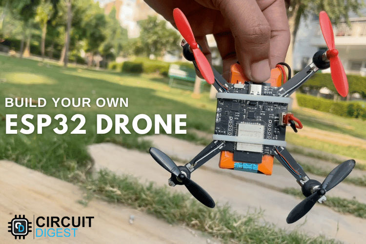
And here is the fully assembled drone.
The images below show all the important parts marked on the drone.
Motor Rotation & Propeller Direction Configuration
Install A and B propellers according to the figure below. During the power-on self-test, check if the propellers spin properly and are spinning in the correct direction. The ESP32 drone flight controller uses a standard quadcopter X-configuration where diagonal motors rotate in the same direction.
ESP32 Drone Code and Firmware Programming
Programming the ESP32 drone controller requires either building from source using ESP-IDF or flashing pre-compiled firmware binaries. The firmware from our DIY drone is based on the ESP-drone firmware from Espressif. The code is written with ESP-IDF, and the version that is used to compile this code is ESP-IDF 4.4.5. Follow the following link to install and configure ESP32 IDF version 4.4.5. You can either build the firmware from scratch using the source provided at the GitHub repo below, or you can just flash the binary file provided within the same repo if you don’t want the hassle. Make sure to use the source code provided on GitHub below, because there are many modifications to Espressif’s code to suit our PCB design.
Three Methods to Flash ESP32 Drone Firmware
Technologies used
Hardware components
- ESP32
- ESP8266
- Arduino
- DHT22
- Relay
- OLED
- NodeMCU
Software & tools
- Arduino IDE
- Blynk
- Firebase Console
- Node-RED
- MQTT Broker
Project demo video
What you get
- Working project / hardware kit, tested before delivery
- Complete source code with explanation
- Project demo and guidance for your viva
- Project report, PPT and IEEE paper support (on request)
Related IoT projects

DIY IoT Plant Watering System using Arduino
A remote plant-watering system that monitors soil moisture and lets you trigger a water pump from anywhere through the Blynk app, with LED-m...
View project
Build a smart mirror with an Arduino UNO Q
A wall-mounted smart mirror that shows the time, calendar, to-do list, room temperature/humidity and weather forecast behind a two-way glass...
View project
ESP32 Patient Health Monitor ECG SpO2 BPM Live Dashboard
Build a complete patient health monitoring system using ESP32 with AD8232 ECG sensor, MAX30102 pulse oximeter, BME280 and live web dashboard...
View project
IoT AC Energy Meter with PZEM-004T and ESP32 WebServer
Build an IoT-based AC energy meter using ESP32 and PZEM-004T to measure voltage, current, power, frequency and energy with live web dashboar...
View project