



Interfacing OLED Display with ESP32
In this article, we will discuss how OLED Display module works, how to interface it with ESP32 and we will also learn to display text and characters on OLED Display module.
- Suitable forB.Tech IoT students
- Build time3-4 weeks
- LevelIntermediate
- Available atAjvika Labs, Kakinada
About this project
As we know that visual aids like displays are inevitable in any Human Machine Interfacing. They are in every electronics nowadays, from simple toys to smartphones, computers, and even critical lifesaving medical devices. The displays will make it easier for the device to convey all of the information it has to provide to the user. If you look at displays, there are multiple types of displays available in the market. From basic seven-segment displays to advanced AMOLED displays. In this tutorial, we are going to look into such a type of display, which is known as OLED or Organic Light Emitting Diode display.
OLED Display Module Pinout
The OLED module we are going to use leverages I2C for communication with the microcontroller. You can also find similar displays with either I2C or SPI interface or even with both in the same PCB. The module we are using has 4 pins in total. And the pinout of a OLED Display Module is shown below-
GND Ground connection for the module. Connect to the GND pin of the ESP32 Devkit.
VCC Provides power for the module. Connect to the 3.3V pin of the ESP32 Devkit.
SCL Serial Clock pin. Used for providing clock pulse for I2C Communication.
SDA Serial Data pin. Used for transferring Data through I2C communication.
Keep in mind that some display module in the market comes with the pin positions swapped. So always check the pin labeling on the silkscreen before making the connections. Some modules come with a 3.3V regulator on boards and some don’t. If your module doesn’t have this regulator onboard, use the module only with 3.3V devices. Otherwise, you may end up damaging them. If it has the regulator with the marking 662K you can use it with 5V devices.
The below image shows the components on the OLED display module PCB.
The XC6206P332 Voltage regulator steps down the input voltage to 3.3V. The inclusion of this voltage regulator allows us to interface the OLED module to even 5.5V microcontrollers or circuits. We can also set the OLED module I2C address by changing the position of the address select resistor. IIC default address is 0x78 (0x3C in 7 -bit) and can be changed to 0x7A (0x3D in 7 -bit).
Circuit Diagram for 0.96” OLED Module
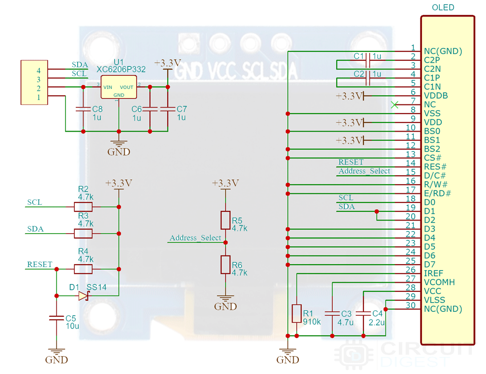
The Schematic diagram for the OLED module is given below. The circuit consists of bare minimum components.
As you can see the board contains very few components. Most of them are complimentary resistors and capacitors which are necessary for the SSD1306 display controller in the OLED panel. Other components include the 3.3V voltage regulator (XC6206P332), pullup resistors for the I2C line, and the address select resistor.
Commonly Asked Questions when using OLED Display with ESP32
OLED is an Organic Light-Emitting Diode. OLED Display is a self-light-emitting technology composed of a thin, multi-layered organic film placed between an anode and cathode. In contrast to LCD technology, OLED does not require a backlight.
SSD1306 and SH1106 are the most commonly used display controllers in the small OLED modules.
The OLED modules support I2C or SPI protocols.
Even though OLED displays are available in different sizes and resolutions, the most commonly used ones are 0.96” and 1.3” modules with 128x64 Dpi resolution. Modules with a resolution of 128x32 are also common in the DIY community.
ESP32 OLED Module Interfacing Connection Diagram
The following image shows how to connect the OLED module with ESP32 Devkit.
Since we are using the OLED module with the I2C protocol, we only need 4 wires for the connections. The VCC and GND pins are connected to the 3.3V and GND pins of the ESP32 Devkit respectively. The SCL pin is connected to the GPIO22 and the SDA pin to the GIPO21.
Arduino Code for Interfacing OLED Display with ESP32
As the connections are made, let’s look at the coding part. To make the interfacing easier we need to install two Arduino libraries Adafruit’s SSD1306 library and Adafruit GFX Library. To install them navigate to the Sketch > Include Library > Manage Libraries. Wait for the Library Manager to download the libraries index and update the list of installed libraries. Then search for the specific library and install it.
Testing the OLED Display
To test and make sure the display is working fine, first make the connections as per the connection diagram provided. Once it’s done, open the example program by navigating to File > Examples > Adafruit SSD1306 >ssd1306_128x64_i2c. Once the example file is opened change the address of the OLED to 0x3C. Then compile and upload the program to the ESP32. The result will be as below-
Arduino Code with Basic Text and Graphics Functions
To learn the basic functions, copy and paste the following code to the Arduino IDE and upload it to the ESP32. The result is as below-
Now let’s look at the code. As usual at the starting, we need to include all the necessary libraries and we must declare any global variable.
In the above section, we have included the wire.h library because we are going to use the I2C protocol and also included the Adafruit libraries necessary for the communication.
Here we have defined the screen resolution as SCREEN_WIDTH and SCREEN_HIGHT. And since we don’t use the reset pin, we declared its value to be -1 so that the library won’t miss behaving. Next, we have changed the OLED address to 0x3C. Change this according to your display module. If you are not sure you can use the I2C scanner example to identify the module’s I2C address. Then we created an instance called to display to use all along with the program. We will use this instance to access all the Adafruit GFX library features.
At the start of the setup function, we have initialized the serial communication and initialized the Adafruit GFX library too. Then we cleared the display buffer with the help clearDisplay function. This will clear any data that’s on the display if the display is not reset previously. We will be using this function all along the code to clear anything on the display. Now let’s look at each section and what’s their functions.
The above section will print the word Hello world! to the OLED display. Before printing the text, we have called a few other functions. The display.setTextSize(size) will set the text size, the display.setTextColor(colour) will set the text colour to white, and finally the display.setCursor(x, y) sets the cursor to the position that corresponds to the x, y coordinates we have provided. Once the print function is called we will call the display.display() that will tell the display controller to display the buffer content on the screen. The display won’t show what we have transferred to the buffer unless this function is called.
In this section, we have used the setTextcolor function to declare the text color as well as the text background color. This will print the text in black color with a white text background.
This section demonstrates how to change the text size. You can see that the text size doubled when we increased the value we passed to the setTextSize function.
This is also similar to displaying a text. You can simply use the print or println function to print the value to the display.
This will help you print any numbers as it is. For example, if you want to print a Hex value, you can do that by simply mentioning the base within the print or println function. The format is as follows print(value, base).
The font files not only contain the alphanumeric characters but also small symbols or graphical characters too. To display them we can use the write function. You can display any ASCII charter in your font file by just writing the ASCII code for that specific character. In the example, we have printed the smiley face which has the ASCII code 0x01. Below is the ASCII character table for the default font used with the Adafruit GFX library. You can use your own font files and they may contain different Glyphs with different ASCII codes.
Just like in the character LCDs we can also scroll text or even the entire screen with the Adafruit GFX library. The startscrollright and startscrollleft functions will scroll the display to right or left respectively. The values within the functions are the start and end page numbers. The current values in the code will scroll the entire display i.e. the whole 8 pages.
The function is simple. You will need to specify the coordinate of the top left corner and the width, height, and color of the rectangle as follows drawRect(x, y, width, height, colour).
The function is similar to the drawRect function, the only difference is that it will fill up the rectangle. You will need to specify the coordinate of the top left corner and the width, height, and color of the rectangle as follows fillRect(x, y, width, height, colour).
The function is also similar to the drawRect function. You will need to specify the coordinate of the top left corner and the width, height, radius of the corner, and color of the rectangle as follows drawRoundRect (x, y, width, height, radius, colour).
The function is also similar to the drawRoundRect function, the only difference is that it will fill up the rounded rectangle. You will need to specify the coordinate of the top left corner and the width, height, radius of the corner, and color of the rectangle as follows fillRoundRect (x, y, width, height, radius, colour).
To draw a circle we can use the drawCircle function. This function requires three parameters – the x and y coordinates for the center point and the radius of the circle. The function format is drawCircle(x, y, Radius).
To draw a filled circle, we can use the fillCircle function. This function requires three parameters – the x and y coordinates for the centre point and the radius of the circle. The function format is fillCircle(x, y, Radius).
To draw a triangle, the drawTriangle function requires a full set of seven parameters: the X, and Y coordinates for three corner points defining the triangle, followed by the colour. The format is drawTriangle(x1, y1, x2, y2, x3, y3, Colour).
Similar to the drawTriangle function, the fillTriangle function also requires a full set of seven parameters: the X, and Y coordinates for three corner points defining the triangle, followed by the color. The format is fillTriangle(x1, y1, x2, y2, x3, y3, Colour).
Displaying Image on OLED Display
To display an image, first, you need to make sure its resolution is within the OLED size. For our example, we will need to resize any image that we are going to use to a resolution of 128x64 pixels. After that, we will need to convert this to a hex data array so that we can store this image in the code and can recall it whenever is needed. There are multiple ways to do all these and I’m going to show you the easiest of them. For that go to the Image2cpp website and upload your picture.
Set the canvas type size to 128 x 64. You can resize the image using the scaling option. Change all other settings until you are satisfied with the preview. Once you are done with all the changes select Arduino code as Code output format and click on generate code button. The corresponding array containing image data will be displayed below. Copy this code and past it to the global variable section of the code. Once done use the array name with the drawBitmap(x, y, array_name, Width, Hieght, Colour) function. Here is the whole code for displaying the image. Change the image array according to you to display your favorite image.
And here is the result.
Projects Using ESP32 and OLED Display Module
There are some interesting projects done with the ESP32 and OLED display. If you want to know more about those topics, links are given below.
In this tutorial, you will learn about Real Time Clock (RTC) and its interfacing with the ESP32 and OLED display. Also we explained how to build digital real time clock with ESP32 and OLED Display
We build Internet clock without using RTC module. This is more accurate as compare to RTC clock. ESP32 is a Wi-Fi module and can be easily connected to the internet so we will use NTP and UDP Protocol to fetch Time from the internet using Wi-Fi.
We build a Biometric Attendance System using ESP32 and OLED Display Module which can store the attendance records in google sheets.
Complete Project Code
OLED Display Module Pinout
The OLED module we are going to use leverages I2C for communication with the microcontroller. You can also find similar displays with either I2C or SPI interface or even with both in the same PCB. The module we are using has 4 pins in total. And the pinout of a OLED Display Module is shown below-
GND Ground connection for the module. Connect to the GND pin of the ESP32 Devkit.
VCC Provides power for the module. Connect to the 3.3V pin of the ESP32 Devkit.
SCL Serial Clock pin. Used for providing clock pulse for I2C Communication.
SDA Serial Data pin. Used for transferring Data through I2C communication.
Keep in mind that some display module in the market comes with the pin positions swapped. So always check the pin labeling on the silkscreen before making the connections. Some modules come with a 3.3V regulator on boards and some don’t. If your module doesn’t have this regulator onboard, use the module only with 3.3V devices. Otherwise, you may end up damaging them. If it has the regulator with the marking 662K you can use it with 5V devices.
The below image shows the components on the OLED display module PCB.
The XC6206P332 Voltage regulator steps down the input voltage to 3.3V. The inclusion of this voltage regulator allows us to interface the OLED module to even 5.5V microcontrollers or circuits. We can also set the OLED module I2C address by changing the position of the address select resistor. IIC default address is 0x78 (0x3C in 7 -bit) and can be changed to 0x7A (0x3D in 7 -bit).
Circuit Diagram for 0.96” OLED Module
The Schematic diagram for the OLED module is given below. The circuit consists of bare minimum components.
As you can see the board contains very few components. Most of them are complimentary resistors and capacitors which are necessary for the SSD1306 display controller in the OLED panel. Other components include the 3.3V voltage regulator (XC6206P332), pullup resistors for the I2C line, and the address select resistor.
Commonly Asked Questions when using OLED Display with ESP32
OLED is an Organic Light-Emitting Diode. OLED Display is a self-light-emitting technology composed of a thin, multi-layered organic film placed between an anode and cathode. In contrast to LCD technology, OLED does not require a backlight.
SSD1306 and SH1106 are the most commonly used display controllers in the small OLED modules.
The OLED modules support I2C or SPI protocols.
Even though OLED displays are available in different sizes and resolutions, the most commonly used ones are 0.96” and 1.3” modules with 128x64 Dpi resolution. Modules with a resolution of 128x32 are also common in the DIY community.
ESP32 OLED Module Interfacing Connection Diagram
The following image shows how to connect the OLED module with ESP32 Devkit.
Since we are using the OLED module with the I2C protocol, we only need 4 wires for the connections. The VCC and GND pins are connected to the 3.3V and GND pins of the ESP32 Devkit respectively. The SCL pin is connected to the GPIO22 and the SDA pin to the GIPO21.
Arduino Code for Interfacing OLED Display with ESP32
As the connections are made, let’s look at the coding part. To make the interfacing easier we need to install two Arduino libraries Adafruit’s SSD1306 library and Adafruit GFX Library. To install them navigate to the Sketch > Include Library > Manage Libraries. Wait for the Library Manager to download the libraries index and update the list of installed libraries. Then search for the specific library and install it.
Testing the OLED Display
To test and make sure the display is working fine, first make the connections as per the connection diagram provided. Once it’s done, open the example program by navigating to File > Examples > Adafruit SSD1306 >ssd1306_128x64_i2c. Once the example file is opened change the address of the OLED to 0x3C. Then compile and upload the program to the ESP32. The result will be as below-
Arduino Code with Basic Text and Graphics Functions
To learn the basic functions, copy and paste the following code to the Arduino IDE and upload it to the ESP32. The result is as below-
Now let’s look at the code. As usual at the starting, we need to include all the necessary libraries and we must declare any global variable.
In the above section, we have included the wire.h library because we are going to use the I2C protocol and also included the Adafruit libraries necessary for the communication.
Here we have defined the screen resolution as SCREEN_WIDTH and SCREEN_HIGHT. And since we don’t use the reset pin, we declared its value to be -1 so that the library won’t miss behaving. Next, we have changed the OLED address to 0x3C. Change this according to your display module. If you are not sure you can use the I2C scanner example to identify the module’s I2C address. Then we created an instance called to display to use all along with the program. We will use this instance to access all the Adafruit GFX library features.
At the start of the setup function, we have initialized the serial communication and initialized the Adafruit GFX library too. Then we cleared the display buffer with the help clearDisplay function. This will clear any data that’s on the display if the display is not reset previously. We will be using this function all along the code to clear anything on the display. Now let’s look at each section and what’s their functions.
The above section will print the word Hello world! to the OLED display. Before printing the text, we have called a few other functions. The display.setTextSize(size) will set the text size, the display.setTextColor(colour) will set the text colour to white, and finally the display.setCursor(x, y) sets the cursor to the position that corresponds to the x, y coordinates we have provided. Once the print function is called we will call the display.display() that will tell the display controller to display the buffer content on the screen. The display won’t show what we have transferred to the buffer unless this function is called.
In this section, we have used the setTextcolor function to declare the text color as well as the text background color. This will print the text in black color with a white text background.
This section demonstrates how to change the text size. You can see that the text size doubled when we increased the value we passed to the setTextSize function.
This is also similar to displaying a text. You can simply use the print or println function to print the value to the display.
This will help you print any numbers as it is. For example, if you want to print a Hex value, you can do that by simply mentioning the base within the print or println function. The format is as follows print(value, base).
The font files not only contain the alphanumeric characters but also small symbols or graphical characters too. To display them we can use the write function. You can display any ASCII charter in your font file by just writing the ASCII code for that specific character. In the example, we have printed the smiley face which has the ASCII code 0x01. Below is the ASCII character table for the default font used with the Adafruit GFX library. You can use your own font files and they may contain different Glyphs with different ASCII codes.
Just like in the character LCDs we can also scroll text or even the entire screen with the Adafruit GFX library. The startscrollright and startscrollleft functions will scroll the display to right or left respectively. The values within the functions are the start and end page numbers. The current values in the code will scroll the entire display i.e. the whole 8 pages.
The function is simple. You will need to specify the coordinate of the top left corner and the width, height, and color of the rectangle as follows drawRect(x, y, width, height, colour).
The function is similar to the drawRect function, the only difference is that it will fill up the rectangle. You will need to specify the coordinate of the top left corner and the width, height, and color of the rectangle as follows fillRect(x, y, width, height, colour).
The function is also similar to the drawRect function. You will need to specify the coordinate of the top left corner and the width, height, radius of the corner, and color of the rectangle as follows drawRoundRect (x, y, width, height, radius, colour).
The function is also similar to the drawRoundRect function, the only difference is that it will fill up the rounded rectangle. You will need to specify the coordinate of the top left corner and the width, height, radius of the corner, and color of the rectangle as follows fillRoundRect (x, y, width, height, radius, colour).
To draw a circle we can use the drawCircle function. This function requires three parameters – the x and y coordinates for the center point and the radius of the circle. The function format is drawCircle(x, y, Radius).
To draw a filled circle, we can use the fillCircle function. This function requires three parameters – the x and y coordinates for the centre point and the radius of the circle. The function format is fillCircle(x, y, Radius).
To draw a triangle, the drawTriangle function requires a full set of seven parameters: the X, and Y coordinates for three corner points defining the triangle, followed by the colour. The format is drawTriangle(x1, y1, x2, y2, x3, y3, Colour).
Similar to the drawTriangle function, the fillTriangle function also requires a full set of seven parameters: the X, and Y coordinates for three corner points defining the triangle, followed by the color. The format is fillTriangle(x1, y1, x2, y2, x3, y3, Colour).
Displaying Image on OLED Display
To display an image, first, you need to make sure its resolution is within the OLED size. For our example, we will need to resize any image that we are going to use to a resolution of 128x64 pixels. After that, we will need to convert this to a hex data array so that we can store this image in the code and can recall it whenever is needed. There are multiple ways to do all these and I’m going to show you the easiest of them. For that go to the Image2cpp website and upload your picture.
Set the canvas type size to 128 x 64. You can resize the image using the scaling option. Change all other settings until you are satisfied with the preview. Once you are done with all the changes select Arduino code as Code output format and click on generate code button. The corresponding array containing image data will be displayed below. Copy this code and past it to the global variable section of the code. Once done use the array name with the drawBitmap(x, y, array_name, Width, Hieght, Colour) function. Here is the whole code for displaying the image. Change the image array according to you to display your favorite image.
And here is the result.
Projects Using ESP32 and OLED Display Module
There are some interesting projects done with the ESP32 and OLED display. If you want to know more about those topics, links are given below.
In this tutorial, you will learn about Real Time Clock (RTC) and its interfacing with the ESP32 and OLED display. Also we explained how to build digital real time clock with ESP32 and OLED Display
We build Internet clock without using RTC module. This is more accurate as compare to RTC clock. ESP32 is a Wi-Fi module and can be easily connected to the internet so we will use NTP and UDP Protocol to fetch Time from the internet using Wi-Fi.
We build a Biometric Attendance System using ESP32 and OLED Display Module which can store the attendance records in google sheets.
Complete Project Code
Technologies used
Hardware components
- ESP32
- ESP8266
- Arduino
- DHT22
- Relay
- OLED
- NodeMCU
Software & tools
- Arduino IDE
- Blynk
- Firebase Console
- Node-RED
- MQTT Broker
What you get
- Working project / hardware kit, tested before delivery
- Complete source code with explanation
- Project demo and guidance for your viva
- Project report, PPT and IEEE paper support (on request)
Delivery & Payment
Delivery takes a minimum of two weeks from the date your inquiry is confirmed.
Payment is in two parts:
• 50% advance to start the project
• Remaining 50% before delivery
Note:
• Documentation and PPT are not included by default
• If you need documentation/PPT, it can be arranged for extra time and cost
We'll confirm the exact timeline and cost with you after reviewing your requirements.
Related IoT projects

IoT
DIY IoT Plant Watering System using Arduino
A remote plant-watering system that monitors soil moisture and lets you trigger a water pump from anywhere through the Blynk app, with LED-m...
View project
IoT
Build a smart mirror with an Arduino UNO Q
A wall-mounted smart mirror that shows the time, calendar, to-do list, room temperature/humidity and weather forecast behind a two-way glass...
View project
IoT
ESP32 Patient Health Monitor ECG SpO2 BPM Live Dashboard
Build a complete patient health monitoring system using ESP32 with AD8232 ECG sensor, MAX30102 pulse oximeter, BME280 and live web dashboard...
View project
IoT
IoT AC Energy Meter with PZEM-004T and ESP32 WebServer
Build an IoT-based AC energy meter using ESP32 and PZEM-004T to measure voltage, current, power, frequency and energy with live web dashboar...
View project