


iN-Car Drowsiness Detection and Alert System with CAN Bus Integration
An advanced in-car drowsiness detection system with CAN bus integration leverages eye-tracking data in automotive grids. Key components include a camera, onboard computer, and alert modules for real-time safety
- Suitable forB.Tech IoT students
- Build time3-4 weeks
- LevelIntermediate
- Available atAjvika Labs, Kakinada
About this project
Camera Module Part Number: Logitech C270 or similar
Microcontroller / Processor Part Number: ESP32-WROOM-32 and Sipeed Maixduino Dev. Kit
CAN Bus Module (Optional for Vehicle Integration) Part Number: MCP2515
Alert Mechanism - Buzzer
Alert Mechanism - LED Indicators Part Number: 5mm LED
Component Selection Rationale:
Camera Module: Provides the video feed for eye detection.
ESP32: Serves as the processing unit for running the detection algorithm and handling communication tasks.
Voltage Regulator & Power Module: Ensures stable power supply, critical for consistent operation.
CAN Bus Module: Facilitates vehicle integration, allowing data sharing with other automotive systems.
Alert Mechanisms: Buzzer, LEDs, and speakers provide real-time feedback based on the eye status.
Passive Components: Resistors, capacitors, and diodes ensure proper circuit functionality, filtering, and protection.
The camera captures the driver’s eye movements in real-time.
The onboard computer processes the video feed using the provided eye detection algorithm to determine the eye aspect ratio (EAR).
If the EAR falls below the threshold, indicating closed or nearly closed eyes, the system identifies potential drowsiness.
Upon detecting drowsiness, the system sends a signal to the alert system via the CAN bus.
Alerts can include an audible warning, seat vibrations, or visual cues on the dashboard.
For advanced implementations, the system can communicate with vehicle control systems (like lane-keeping assist or cruise control) via the CAN bus to initiate corrective actions, such as slowing down the vehicle.
Ensure the system is connected to the vehicle’s power supply with appropriate fuses and voltage regulators to handle the automotive environment’s power fluctuations.
Integration Challenges:
Vibration and Noise: Automotive environments are noisy and vibrate, which can affect camera stability. Use vibration-damping mounts for the camera.
Temperature Variations: Automotive environments experience extreme temperature variations. Use automotive-grade components designed to operate in such conditions.
Real-Time Processing: Ensure that the onboard computer can handle real-time video processing with minimal latency.
Safety and Compliance: Ensure the system complies with automotive safety standards and does not interfere with critical vehicle systems.
Technologies used
Hardware components
- ESP32
- ESP8266
- Arduino
- DHT22
- Relay
- OLED
- NodeMCU
Software & tools
- Arduino IDE
- Blynk
- Firebase Console
- Node-RED
- MQTT Broker
What you get
- Working project / hardware kit, tested before delivery
- Complete source code with explanation
- Project demo and guidance for your viva
- Project report, PPT and IEEE paper support (on request)
Related IoT projects

DIY IoT Plant Watering System using Arduino
A remote plant-watering system that monitors soil moisture and lets you trigger a water pump from anywhere through the Blynk app, with LED-m...
View project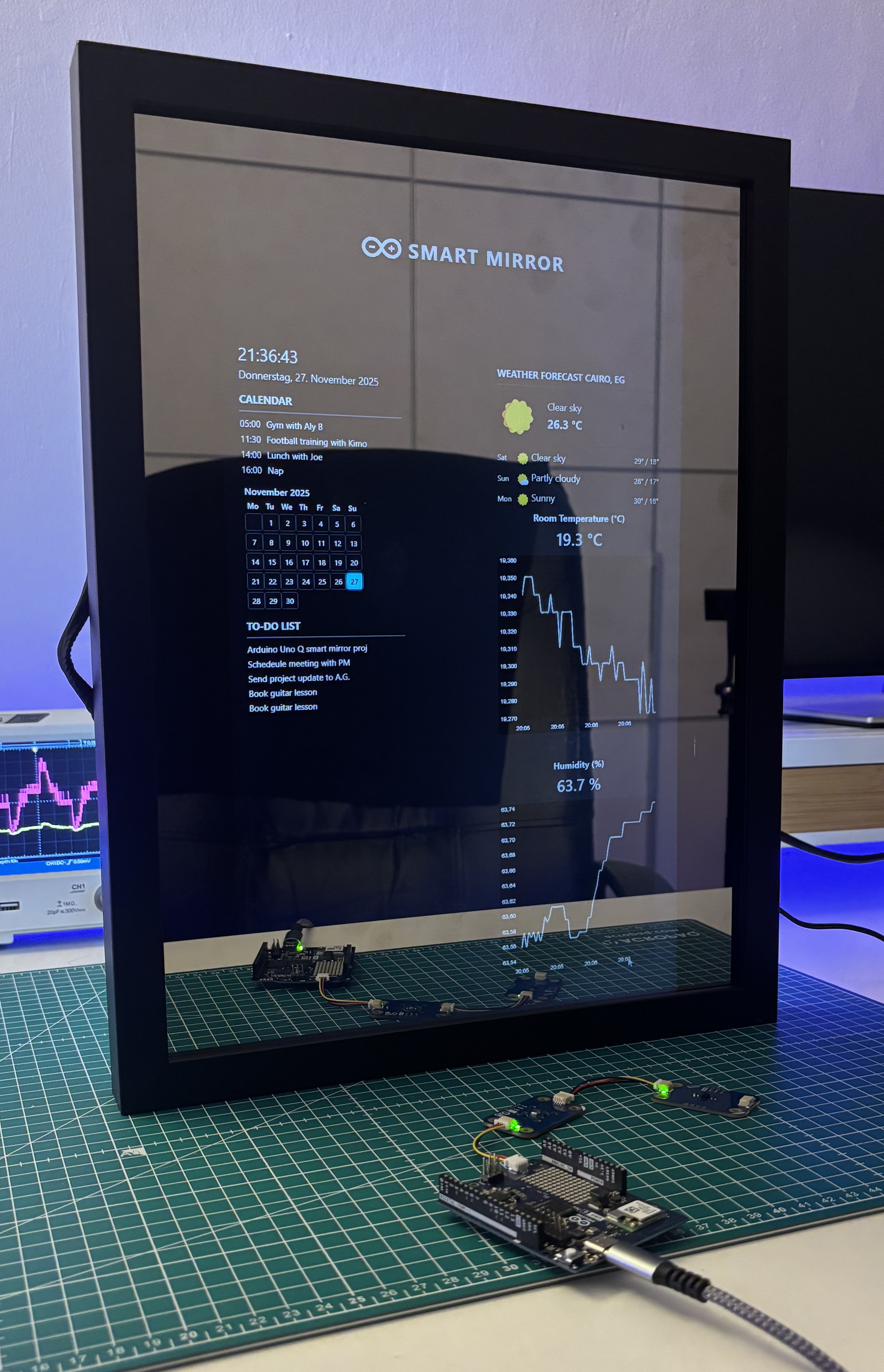
Build a smart mirror with an Arduino UNO Q
A wall-mounted smart mirror that shows the time, calendar, to-do list, room temperature/humidity and weather forecast behind a two-way glass...
View project
ESP32 Patient Health Monitor ECG SpO2 BPM Live Dashboard
Build a complete patient health monitoring system using ESP32 with AD8232 ECG sensor, MAX30102 pulse oximeter, BME280 and live web dashboard...
View project
IoT AC Energy Meter with PZEM-004T and ESP32 WebServer
Build an IoT-based AC energy meter using ESP32 and PZEM-004T to measure voltage, current, power, frequency and energy with live web dashboar...
View project