
ESP32 Smart Thermostat with TFT Touchscreen
Build a WiFi-connected smart thermostat using ESP32 with 2.8-inch TFT touchscreen to control HVAC systems with scheduling and remote access.
- Suitable forB.Tech IoT students
- Build time4-6 weeks
- LevelAdvanced
- Available atAjvika Labs, Kakinada
About this project
Smart thermostat uses ESP32 with 2.8-inch ILI9341 TFT touchscreen (240x320) and XPT2046 touch controller creating a Nest-like smart thermostat. Current temperature and humidity from DHT22 or BME280. Target temperature set by up/down touch buttons or drag. HVAC control: relay outputs for Heat, Cool, Fan. Safety: minimum on-time 5 minutes to protect compressor. Display: large temperature readout, setpoint, HVAC mode, schedule status. Scheduling: 4 time slots per day, 7 days configurable via web interface. Geo-fencing: phone GPS via IFTTT webhook to detect owner leaving (Away mode) and returning. MQTT integration for Home Assistant. Presence sensor: PIR or mmWave radar to auto-away after 30 minutes no motion. Voice control via Google Assistant / Alexa via Sinric Pro. Libraries: TFT_eSPI, XPT2046_Touchscreen, DHT, PubSubClient, WiFi, NTPClient.
Detailed Project Description
ESP32 Smart Thermostat with TFT Touchscreen focuses on a specific hardware interface or peripheral and shows exactly how to wire it, drive it from firmware and verify it is working.
How It Works
1. The peripheral is connected to the controller using the required bus (SPI/I2C/UART/I2S/CAN/RS-485/PWM/ADC).
2. The driver library is initialised and the peripheral configured.
3. Firmware exchanges data with the peripheral and processes it (measure, decode, render, play).
4. Results are verified on a display, serial monitor or the receiving device.
Key Components and Their Role
- ESP32: dual-core Wi-Fi + Bluetooth microcontroller that runs the firmware, reads the sensors and hosts the network connection.
- DHT22: digital temperature and humidity sensor with better accuracy than DHT11.
- BME280: I2C sensor for temperature, humidity and barometric pressure.
- PIR motion sensor: passive infrared sensor that detects human movement.
- Relay module: electrically isolated switch that lets the controller turn AC/DC loads on and off.
- TFT display: colour graphical display (SPI) used for the on-device user interface.
- GPS module (NEO-6M): receiver that provides latitude, longitude, speed and time over UART/NMEA.
- MQTT: lightweight publish/subscribe messaging protocol used for IoT data.
Implementation Steps
1. Collect the components and study each module's datasheet (pin-out, voltage, interface).
2. Wire the circuit on a breadboard following the pin mapping; power sensors from the correct rail (3.3 V / 5 V).
3. Install Arduino IDE, TFT_eSPI Library, XPT2046 Library and the required libraries; flash a minimal test sketch for each module separately.
4. Write the main firmware: read sensors → process → drive outputs / send data.
5. Configure network or cloud credentials and test communication end-to-end.
6. Calibrate thresholds, add error handling (reconnect, sensor time-out) and run a long-duration test.
7. Finalise on a PCB / enclosure and document wiring, code and results.
Key Features
- Correct wiring and bus configuration
- Driver setup
- Data processing
- Verification on real hardware
Expected Output
On completion the student will have a working peripheral that is measured/driven exactly as intended.
Deliverables
- Complete source code with comments
- Circuit diagram and pin mapping
- Project report with screenshots and results
- Demonstration-ready build
Technologies used
Hardware components
- ESP32 DevKit
- 2.8 inch ILI9341 TFT Touch Display
- DHT22 Sensor
- 3-Channel Relay Module
- PIR Sensor
Software & tools
- Arduino IDE
- TFT_eSPI Library
- XPT2046 Library
- Home Assistant
What you get
- Working project / hardware kit, tested before delivery
- Complete source code with explanation
- Project demo and guidance for your viva
- Project report, PPT and IEEE paper support (on request)
Delivery & Payment
Delivery takes a minimum of two weeks from the date your inquiry is confirmed.
Payment is in two parts:
• 50% advance to start the project
• Remaining 50% before delivery
Note:
• Documentation and PPT are not included by default
• If you need documentation/PPT, it can be arranged for extra time and cost
We'll confirm the exact timeline and cost with you after reviewing your requirements.
Related IoT projects

IoT
DIY IoT Plant Watering System using Arduino
A remote plant-watering system that monitors soil moisture and lets you trigger a water pump from anywhere through the Blynk app, with LED-m...
View project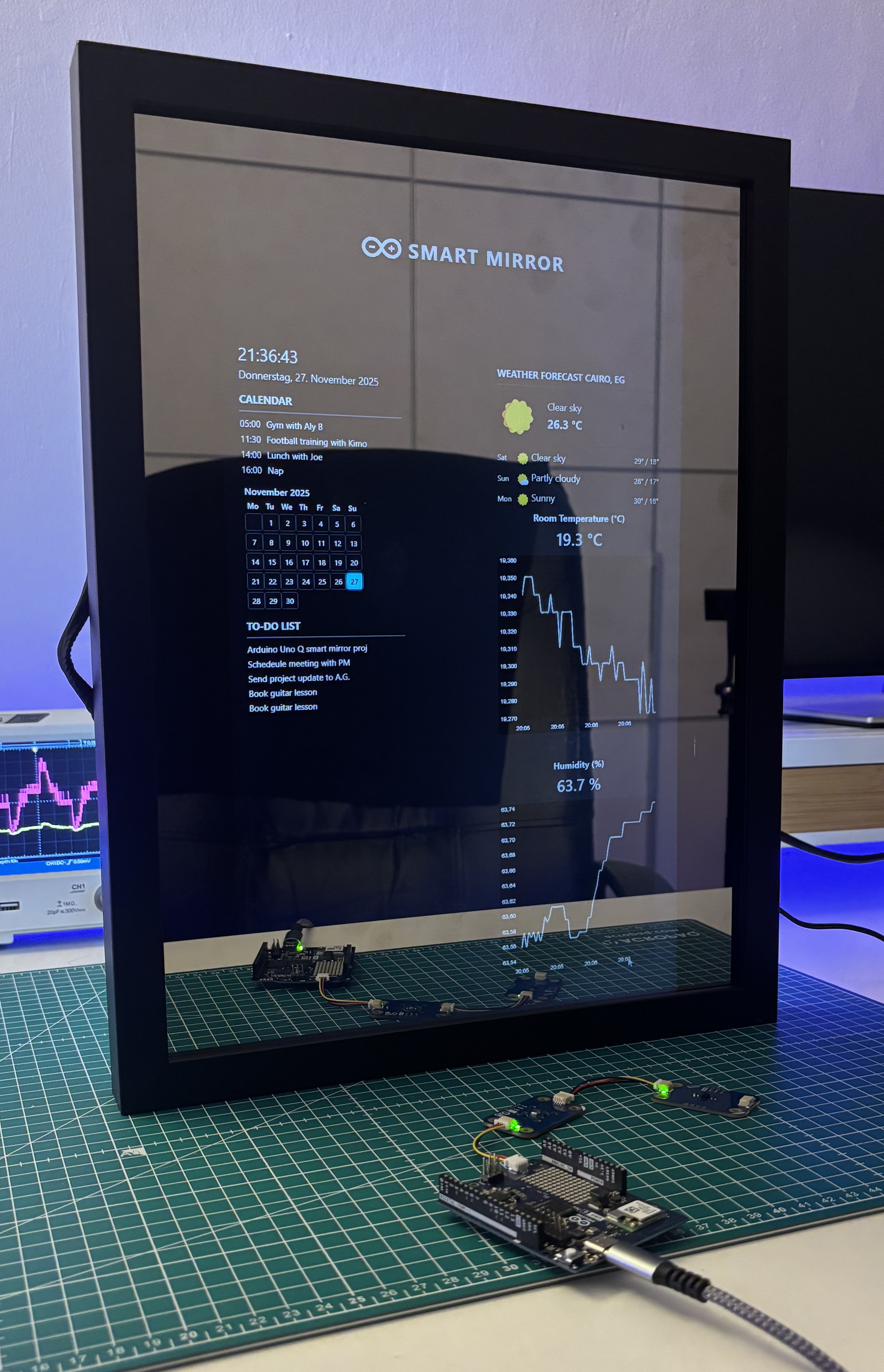
IoT
Build a smart mirror with an Arduino UNO Q
A wall-mounted smart mirror that shows the time, calendar, to-do list, room temperature/humidity and weather forecast behind a two-way glass...
View project
IoT
ESP32 Patient Health Monitor ECG SpO2 BPM Live Dashboard
Build a complete patient health monitoring system using ESP32 with AD8232 ECG sensor, MAX30102 pulse oximeter, BME280 and live web dashboard...
View project
IoT
IoT AC Energy Meter with PZEM-004T and ESP32 WebServer
Build an IoT-based AC energy meter using ESP32 and PZEM-004T to measure voltage, current, power, frequency and energy with live web dashboar...
View project