



ESP RainMaker Getting Started with ESP32
In this tutorial, we are going to look at the ESP RainMaker. ESP RainMaker is the end-to-end platform for the ESP chips from Experessif. It is designed as a successor to Experessif’s ESP Jumpstart platform.
- Suitable forB.Tech IoT students
- Build time3-4 weeks
- LevelIntermediate
- Available atAjvika Labs, Kakinada
About this project
The ESP Rainmaker is similar to other IoT services like the Blynk application, Ubidots, Thingspeak, IFTTT, Arduino IoT cloud, etc. But this platform offers more features such as self-adapting mobile apps, free integration of Alexa and Google Assistant, Node sharing, Wi-Fi provisioning through QR code, and much more. The great attribute of using this IoT platform is that it is free for its users and offers great features. The primary components of this solution are:
Claiming Service (to get the Cloud connectivity credentials)
RainMaker Agent (i.e. Rainmaker repo, to develop the firmware)
RainMaker Cloud (backend, offering remote connectivity)
RainMaker Phone App/CLI (Client utilities for remote access)
ESP Rainmaker Features and Benefits
A few main features and benefits of the ESP RainMaker platform are as follows:
Minimal R&D investment due to the turnkey solution.
Safe and stable upscale options.
Reduced development time.
Maintenance-free, riskless cloud solution.
Pay-as-you-use solution based on AWS serverless architecture.
Private cloud solution for better security and privacy.
Supports most mainstream services such as Alexa, Google Assistant, Apple Homekit, and Matter.
Node sharing – This allows users to share their device’s control over the internet.
Timezone setting – the timezone of each device or node can be changed through the phone app instead of hard coding.
Arduino Support – ESP rainmaker now supports Arduino IDE, which is great news for the DIY community.
Node grouping – Users can now manage nodes as a group, which enables the users to manage multiple devices with ease.
FaaS — Function As A Service - In addition to managed services, the Serverless architecture offers a “FaaS (Function-as-a-Service)” runtime that allows developers to write code snippets that can work on the data and interact with available services. Developers can use their familiar programming languages (such as Python, node.js and Go) with SDKs to interact with services. FaaS is also charged based on the number of executions and time and memory consumption of the runtime.
ESP RainMaker Workflow
Now let’s look at the simple workflow of the Rainmaker and how it works.
Once the ESP32 is programmed with ESP RainMaker firmware, the ESP32 will generate and display a QR code in the serial monitor which can be scanned using the ESP rainmaker app.
Once the QR code is scanned the app will initiate BLE communication with the ESP32 SoC.
After connecting with the ESP32 we can start provisioning the SoC by providing the WiFi credentials.
The ESP32 will establish the connection to the ESP RainMaker Cloud through the WiFi and will exchange the relevant data we have programmed to do.
Once the ESP32 is connected to the cloud we can communicate it through either the cloud service or the mobile app.
Circuit Diagram for the ESP RainMaker Example
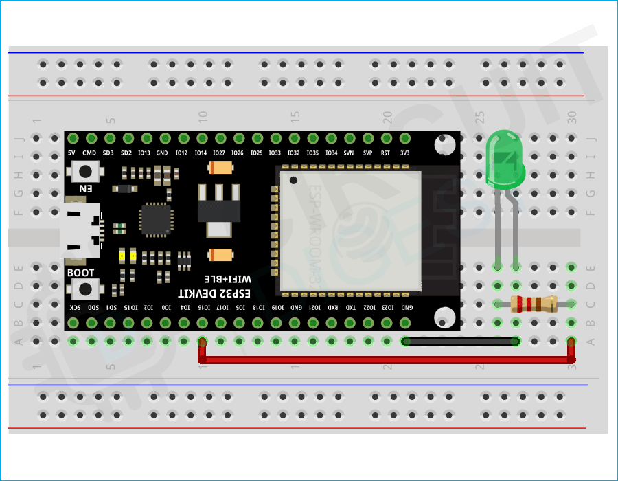
We have already build a lot of interesting projects using ESP32. Now in this article lets start with the basics again by interfacing an LED with ESP32, but this time using ESP32 with Rainmaker. For that, connect an LED to the GPIO16 through a current limit resistor as shown below. And for the switch, we will use the onboard boot switch.
Here is how the real-life connection looks.
Commonly Asked Questions
ESP RainMaker is a platform that allows developers to build connected devices with Espressif's ESP32 SoC without the hassle of managing the infrastructure. It provides a device SDK, self-adapting phone apps, transparent cloud middleware, and host utilities to reduce complexity in the development of connected devices.
ESP RainMaker uses Amazon Web Services (AWS) Servers.
ESP RainMaker will always be available to makers, hobbyists, and teachers, for free. They also offer paid services without the limitations of public service.
Using ESP RainMaker with Arduino IDE
Now let’s look at how we can use the ESP RainMaker with the Arduino IDE. For that, we must install the ESP32 board V2.0. If you have already installed the V2.0 you can skip this step. If you have an old version, update the board definition to the latest one. If you don’t have the ESP32 board installed or if the board manager is not showing version 2.0, install it using the following Jason link.
https://raw.githubusercontent.com/espressif/arduino-esp32/gh-pages/package_esp32_index.json
To install the board, add the above link to the additional board manager URLs section in the Arduino IDE preferences menu as shown below.
After that Search for ESP32 in the board manager and install the latest version. Then in the IDE, select board as ESP32 Dev Module, flash size as per your board, and the partition scheme as RainMaker. Once it’s done, open the example code attached below this article, compile it, and upload it to the ESP32 development board. Download the ESP RainMaker app . Scan the QR code displayed in the serial Monitor using the Rainmaker APP.
If the QR code is not proper as shown above, copy the URL at the bottom of the serial monitor and paste it to any browser. The browser will now show the correct QR code and you can scan it using the app.
Once it’s done, the ESP will automatically connect to the WiFi network and a new device called Switch will be added to the app’s home screen. From there you can control the LED using the switch button on the device.
Arduino Code for Using ESP RainMaker
Now let’s look at the code.
At the start, we have included all the necessary libraries, which include the WiFi and RainMaker libraries. Later we specified the BLE credentials using the pointers service_name and pop, which will be used while the provisioning. Then we have defined the GPIO pins used for the LED and switch. We have also created a Boolean variable called switch_state to store the switch status.
The sysProvEvent function is used for system provisioning events. This function will obtain the Wi-Fi credentials and connect ESP32 to the router.
The following callback function will be responsible for checking the particular device which sent the data and then changing the parameter of the device accordingly. This callback function will be used for the device LED. If the device is ‘LED’ and its parameter is ‘Power’ then this function will check whether the state of the LED pin is HIGH or LOW. If the power is HIGH, the LED will turn ON. Similarly, if the power is LOW, the LED will turn OFF.
Inside the setup() function, we open the serial communication at a baud rate of 115200. Then we configure the reset pin as an input pin and the LED pin as an output pin. This is done by using pinMode() function and specifying the GPIO pin as the first parameter and the mode as the second parameter. Moreover, we will initially set the LED pin in a LOW state. Then we will declare a node with the name “ESP RainMaker Node”. Later we declared the switch device. We also declared the call-back function for the switch device and enabled the time zone service. Later we started the RainMaker band using Rmaker.start function and called the sysProEvent function after that for provisioning.
In the loop, we will monitor the state of GPIO0 and will update the parameter switch_state accordingly. We will also print the status change to the serial monitor for debugging purposes. And here is the result.
Common Problems and Solutions while Uploading RainMaker Firmware
Solution : Make sure to choose the partitioning scheme with the OTA option. Preferably the RainMaker option itself.
Solution : Enable Erase all flash content before sketch upload.
Solution : Select the proper flash size as per your board and choose the partitioning scheme with the OTA option. Preferably the RainMaker option itself.
Complete Project Code
Technologies used
Hardware components
- ESP32
- ESP8266
- Arduino
- DHT22
- Relay
- OLED
- NodeMCU
Software & tools
- Arduino IDE
- Blynk
- Firebase Console
- Node-RED
- MQTT Broker
What you get
- Working project / hardware kit, tested before delivery
- Complete source code with explanation
- Project demo and guidance for your viva
- Project report, PPT and IEEE paper support (on request)
Related IoT projects

DIY IoT Plant Watering System using Arduino
A remote plant-watering system that monitors soil moisture and lets you trigger a water pump from anywhere through the Blynk app, with LED-m...
View project
Build a smart mirror with an Arduino UNO Q
A wall-mounted smart mirror that shows the time, calendar, to-do list, room temperature/humidity and weather forecast behind a two-way glass...
View project
ESP32 Patient Health Monitor ECG SpO2 BPM Live Dashboard
Build a complete patient health monitoring system using ESP32 with AD8232 ECG sensor, MAX30102 pulse oximeter, BME280 and live web dashboard...
View project
IoT AC Energy Meter with PZEM-004T and ESP32 WebServer
Build an IoT-based AC energy meter using ESP32 and PZEM-004T to measure voltage, current, power, frequency and energy with live web dashboar...
View project