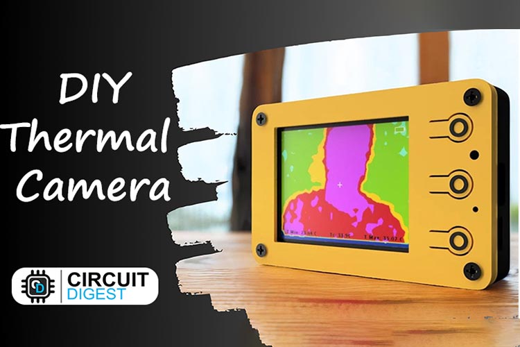


DIY Thermal Camera: Build your Own Infrared Imaging Device with ESP32 and MLX90640 Sensor
Create your own DIY thermal imaging camera using the ESP32 Wrover Module and MLX90640 sensor in affordable cost.
- Suitable forB.Tech IoT students
- Build time3-4 weeks
- LevelIntermediate
- Available atAjvika Labs, Kakinada
About this project
Ditch X-ray vision, thermal cameras are the real industrial superheroes! They don't just see light, they see heat, making them masters of uncovering hidden energy drains, pinpointing overheating gadgets, and even aiding soldiers in the dark. They're invaluable in industries like tech repair, where they sniff out shorted circuits like electronic bloodhounds. The only catch? Their price tag can be a bit frosty. But hey, technology is always evolving, and soon, thermal vision might be just as common as your phone camera! So remember, that seemingly ordinary camera might just be packing some extraordinary heat-sensing powers.
So, in this project, we are going to find some solution for that by making a DIY thermal imager using much cheaper available components. The cheaper thermal imaging sensors we have considered are the AMG8833 from Panasonic, MLX90640 and MLX90641 from Melexis. Even though the AMG8833 is the cheapest of them all it only has a resolution of 8x8, while MLX90640 offers a resolution of 32x24 and MLX90641 offers a resolution of 16x12. Since the MLX90640 offers the best resolution in the price range we choose it for our DIY thermal camera.
Before this we have worked on Thermal Camera with Raspberry Pi and Thermal Camera with Arduino, Be sure to check them out as well.
Features of DIY Thermal camera
Image sensor resolution: 32x24.
Sensor field of view (FoV): 55°x35°
Temperature measurement range: -40 to 300°C
- 40 to 85°C operational temperature range.
Adjustable refresh rate – 4Hz – 32Hz.
10 different colour pallets.
5 different interpolation modes.
2.4” TFT display with 320x240 resolution.
Save thermal image to SD card.
Built-in battery and charging circuit.
Components Required to Build the DIY Thermal Camera
The components required to build the DIY Thermal Camera are listed below. The exact value of each component can be found in the schematics or the BOM.
ESP32 Wrover Module with 8Mb flash and PSRAM – x1
MLX90640 Far infrared thermal sensor array Sensor – x1
2.4” TFT display 320x240 resolution ILI9341 driver – x1
CH340K USB - UART controller – x1
TP4056 Li-ion charger IC – x1
MIC5219-3.3YM5 3.3v LDO – x1
AO3401 P - MOSFET – x1
2n7002DW dual N - MOSFET – x1
S8050 Transistor - x1
Type C USB Connector 16Pin – x1
SMD resistors and capacitors
SMD Tactile switches
3D printed Enclosure and mounting screws
Other tools and consumables.
Circuit Diagram - DIY Thermal Camera
The complete circuit diagram for the DIY Thermal Camera is shown below. It can also be downloaded in PDF format. We have used KiCad to design the schematics and PCB for this project, you can find the complete files on out GitHub page given at the bottom of this article.
Let’s discuss the Schematics section by section for better understanding. A type C USB port is used for both charging as well as programming purposes. The power from the USB port is connected to a power path controller circuit built around a P-Channel MOSFET U2 and a diode D1. When the USB power is available the device will operate from the USB power and also will charge the internal battery, when the USB power is cut, the device will automatically change to battery power. For voltage regulation, we have used a MIC5219 3.3V LDO from Microchip, which is capable of providing up to 500mA of current with a very low dropout voltage of 500mV at full load. A slide switch with a pullup resistor is connected to the enable pin of MIC5219. This switch is used for turning on and off the thermal camera. When this pin is pulled to the ground the LDO will be shut down and hence the other parts of the device too, except the battery charging section. For charging the internal battery we are using a TP4056 charge controller which is capable of a maximum charge current of 1A. For battery voltage sensing we have used a classic voltage divider, which will reduce the battery voltage to a safe level for measurement.
In the next section, we have the ESP32 SoC itself along with the programming circuit and the MLX90640 Far Infrared thermal sensor array. The programming circuit consists of a CH340K USB to UART controller along with a 2N7002DW dual N – N-Channel MOSFET from ON Semi. We chose the CH340K because of its small footprint as well as its low cost. The tiny dual MOSFET will act as an auto-reset circuit for the ESP32 thus removing any need for manual rest or boot selection during programming. Even though the auto-reset works flawlessly, we have also added boot and reset buttons, just in case. The circuit around the ESP32 is standard, just bypass capacitors and pullup resistors. For the image sensor, we have decided to solder it directly to the PCB to make the whole device compact. The sensor is interfaced to the SoC using I2C and only has 4 pins, including power and ground. If we want to use an image sensor module instead of soldering the sensor to the PCB, or if we want to add some other I2C device, we can use the additional I2C connector added to the PCB.
In the last section, we have the TFT display along with the navigation buttons and Micro SD slot. For display, we have used a 2.4” TFT display with a resolution of 320x240. The display uses an ILI9341 driver chip. It is interfaced to the ESP32 using SPI and supports SPI speed up to 65MHz. The display is directly soldered to the PCB. For backlight control, we have used a S8050 transistor. We will be able to control the backlight brightness using PWM signals. The display is connected to the VSPI interface of ESP32 while the Micro SD slot is connected to the HSPI interface. This will ensure that the ESP32 can access or control both the display as well as the SD card at the same time in case needed.
PCB for DIY Thermal Camera
For this project, we have decided to make a custom PCB. This will ensure that the final product is as compact as possible as well as easy to assemble and use. The PCB has a dimension of 80mm x 50mm. Here are the top and bottom layers of the PCB.
And here is the 3D view of the PCB.
Here is the fully assembled PCB.
We have designed a cool-looking 3D-printed enclosure for the DIY thermal camera. The files for all the 3D printed parts can be downloaded from the GitHub link provided at the end of the article along with the Arduino sketch and bitmap file. Learn more about 3D printing and how to get started with it by following the link.
You can get all the STL files from here
And here is the fully assembled DIY Thermal Camera.
DIY Thermal Camera Overview
Here is the overall overview of a fully assembled DIY Thermal Camera.
The button usage is the following.
Up/+ Button : Default : Change/cycle through interpolation mode. In Settings : Change the selected value.
Default : Change/cycle through interpolation mode.
Default : Change/cycle through interpolation mode.
In Settings : Change the selected value.
In Settings : Change the selected value.
Middle/Ok Button : Default : Short press : Save images to SD card. Long Press : Enter the settings menu. In Settings : Short press : Change the selection in the menu. Long Press: Exit the settings menu.
Default : Short press : Save images to SD card. Long Press : Enter the settings menu.
Short press : Save images to SD card.
Short press : Save images to SD card.
Long Press : Enter the settings menu.
Long Press : Enter the settings menu.
In Settings : Short press : Change the selection in the menu. Long Press: Exit the settings menu.
Short press : Change the selection in the menu.
Short press : Change the selection in the menu.
Long Press: Exit the settings menu.
So, in this project, we are going to find some solution for that by making a DIY thermal imager using much cheaper available components. The cheaper thermal imaging sensors we have considered are the AMG8833 from Panasonic, MLX90640 and MLX90641 from Melexis. Even though the AMG8833 is the cheapest of them all it only has a resolution of 8x8, while MLX90640 offers a resolution of 32x24 and MLX90641 offers a resolution of 16x12. Since the MLX90640 offers the best resolution in the price range we choose it for our DIY thermal camera.
Before this we have worked on Thermal Camera with Raspberry Pi and Thermal Camera with Arduino, Be sure to check them out as well.
Features of DIY Thermal camera
Image sensor resolution: 32x24.
Sensor field of view (FoV): 55°x35°
Temperature measurement range: -40 to 300°C
- 40 to 85°C operational temperature range.
Adjustable refresh rate – 4Hz – 32Hz.
10 different colour pallets.
5 different interpolation modes.
2.4” TFT display with 320x240 resolution.
Save thermal image to SD card.
Built-in battery and charging circuit.
Components Required to Build the DIY Thermal Camera
The components required to build the DIY Thermal Camera are listed below. The exact value of each component can be found in the schematics or the BOM.
ESP32 Wrover Module with 8Mb flash and PSRAM – x1
MLX90640 Far infrared thermal sensor array Sensor – x1
2.4” TFT display 320x240 resolution ILI9341 driver – x1
CH340K USB - UART controller – x1
TP4056 Li-ion charger IC – x1
MIC5219-3.3YM5 3.3v LDO – x1
AO3401 P - MOSFET – x1
2n7002DW dual N - MOSFET – x1
S8050 Transistor - x1
Type C USB Connector 16Pin – x1
SMD resistors and capacitors
SMD Tactile switches
3D printed Enclosure and mounting screws
Other tools and consumables.
Circuit Diagram - DIY Thermal Camera
The complete circuit diagram for the DIY Thermal Camera is shown below. It can also be downloaded in PDF format. We have used KiCad to design the schematics and PCB for this project, you can find the complete files on out GitHub page given at the bottom of this article.
Let’s discuss the Schematics section by section for better understanding. A type C USB port is used for both charging as well as programming purposes. The power from the USB port is connected to a power path controller circuit built around a P-Channel MOSFET U2 and a diode D1. When the USB power is available the device will operate from the USB power and also will charge the internal battery, when the USB power is cut, the device will automatically change to battery power. For voltage regulation, we have used a MIC5219 3.3V LDO from Microchip, which is capable of providing up to 500mA of current with a very low dropout voltage of 500mV at full load. A slide switch with a pullup resistor is connected to the enable pin of MIC5219. This switch is used for turning on and off the thermal camera. When this pin is pulled to the ground the LDO will be shut down and hence the other parts of the device too, except the battery charging section. For charging the internal battery we are using a TP4056 charge controller which is capable of a maximum charge current of 1A. For battery voltage sensing we have used a classic voltage divider, which will reduce the battery voltage to a safe level for measurement.
In the next section, we have the ESP32 SoC itself along with the programming circuit and the MLX90640 Far Infrared thermal sensor array. The programming circuit consists of a CH340K USB to UART controller along with a 2N7002DW dual N – N-Channel MOSFET from ON Semi. We chose the CH340K because of its small footprint as well as its low cost. The tiny dual MOSFET will act as an auto-reset circuit for the ESP32 thus removing any need for manual rest or boot selection during programming. Even though the auto-reset works flawlessly, we have also added boot and reset buttons, just in case. The circuit around the ESP32 is standard, just bypass capacitors and pullup resistors. For the image sensor, we have decided to solder it directly to the PCB to make the whole device compact. The sensor is interfaced to the SoC using I2C and only has 4 pins, including power and ground. If we want to use an image sensor module instead of soldering the sensor to the PCB, or if we want to add some other I2C device, we can use the additional I2C connector added to the PCB.
In the last section, we have the TFT display along with the navigation buttons and Micro SD slot. For display, we have used a 2.4” TFT display with a resolution of 320x240. The display uses an ILI9341 driver chip. It is interfaced to the ESP32 using SPI and supports SPI speed up to 65MHz. The display is directly soldered to the PCB. For backlight control, we have used a S8050 transistor. We will be able to control the backlight brightness using PWM signals. The display is connected to the VSPI interface of ESP32 while the Micro SD slot is connected to the HSPI interface. This will ensure that the ESP32 can access or control both the display as well as the SD card at the same time in case needed.
PCB for DIY Thermal Camera
For this project, we have decided to make a custom PCB. This will ensure that the final product is as compact as possible as well as easy to assemble and use. The PCB has a dimension of 80mm x 50mm. Here are the top and bottom layers of the PCB.
And here is the 3D view of the PCB.
Here is the fully assembled PCB.
We have designed a cool-looking 3D-printed enclosure for the DIY thermal camera. The files for all the 3D printed parts can be downloaded from the GitHub link provided at the end of the article along with the Arduino sketch and bitmap file. Learn more about 3D printing and how to get started with it by following the link.
You can get all the STL files from here
And here is the fully assembled DIY Thermal Camera.
DIY Thermal Camera Overview
Here is the overall overview of a fully assembled DIY Thermal Camera.
The button usage is the following.
Up/+ Button : Default : Change/cycle through interpolation mode. In Settings : Change the selected value.
Default : Change/cycle through interpolation mode.
Default : Change/cycle through interpolation mode.
In Settings : Change the selected value.
In Settings : Change the selected value.
Middle/Ok Button : Default : Short press : Save images to SD card. Long Press : Enter the settings menu. In Settings : Short press : Change the selection in the menu. Long Press: Exit the settings menu.
Default : Short press : Save images to SD card. Long Press : Enter the settings menu.
Short press : Save images to SD card.
Short press : Save images to SD card.
Long Press : Enter the settings menu.
Long Press : Enter the settings menu.
In Settings : Short press : Change the selection in the menu. Long Press: Exit the settings menu.
Short press : Change the selection in the menu.
Short press : Change the selection in the menu.
Long Press: Exit the settings menu.
Technologies used
Hardware components
- ESP32
- ESP8266
- Arduino
- DHT22
- Relay
- OLED
- NodeMCU
Software & tools
- Arduino IDE
- Blynk
- Firebase Console
- Node-RED
- MQTT Broker
Project demo video
What you get
- Working project / hardware kit, tested before delivery
- Complete source code with explanation
- Project demo and guidance for your viva
- Project report, PPT and IEEE paper support (on request)
Delivery & Payment
Delivery takes a minimum of two weeks from the date your inquiry is confirmed.
Payment is in two parts:
• 50% advance to start the project
• Remaining 50% before delivery
Note:
• Documentation and PPT are not included by default
• If you need documentation/PPT, it can be arranged for extra time and cost
We'll confirm the exact timeline and cost with you after reviewing your requirements.
Related IoT projects

IoT
DIY IoT Plant Watering System using Arduino
A remote plant-watering system that monitors soil moisture and lets you trigger a water pump from anywhere through the Blynk app, with LED-m...
View project
IoT
Build a smart mirror with an Arduino UNO Q
A wall-mounted smart mirror that shows the time, calendar, to-do list, room temperature/humidity and weather forecast behind a two-way glass...
View project
IoT
ESP32 Patient Health Monitor ECG SpO2 BPM Live Dashboard
Build a complete patient health monitoring system using ESP32 with AD8232 ECG sensor, MAX30102 pulse oximeter, BME280 and live web dashboard...
View project
IoT
IoT AC Energy Meter with PZEM-004T and ESP32 WebServer
Build an IoT-based AC energy meter using ESP32 and PZEM-004T to measure voltage, current, power, frequency and energy with live web dashboar...
View project