
DIY Handheld Retro Gaming Console Using ESP32
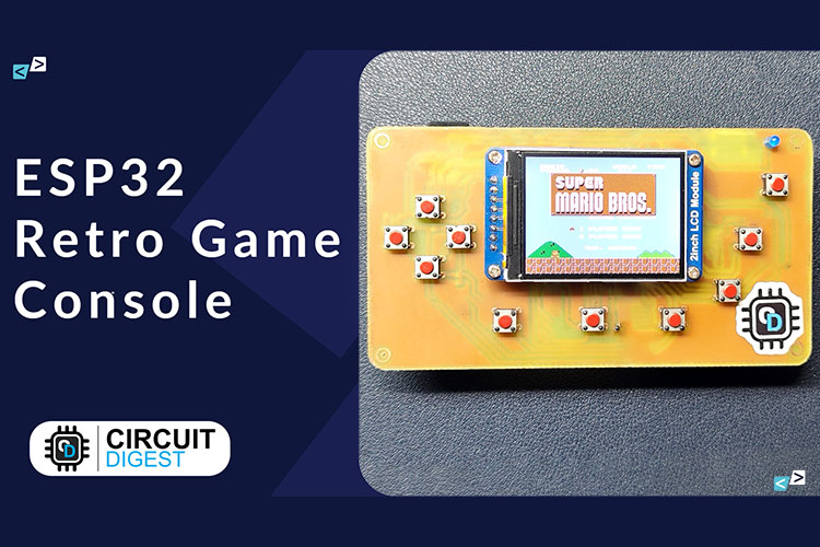
In this article, we are building a retro gaming console with the ESP32. This console is based on the popular Odroid Go, with updated firmware and new IPS display. And the firmware used is a modified version of ducalex's retro-go firmware.
- Suitable forB.Tech IoT students
- Build time3-4 weeks
- LevelIntermediate
- Available atAjvika Labs, Kakinada
About this project
Retro Game Console using ESP32 - Quick Overview
Build Time: 8-12 hours | Cost: $50-80 | Difficulty: Intermediate-Advanced
What You'll Learn: ESP32 programming, SPI communication, PCB design, Firmware modification
Applications: Retro gaming, Portable entertainment, Emulator development, DIY electronics
└ Supported Gaming Systems
Building an ESP32 handheld game console requires carefully selected components. We designed this circuit with generic components or modules, making the replication process easy.
ESP32 Wrover Kit with 16MB flash – 1
ESP32 Wrover Kit with 16MB flash – 1
Waveshare 2” 320x240 IPS display module with ST7789V driver – 1
Waveshare 2” 320x240 IPS display module with ST7789V driver – 1
TP4056 module with protection – 1
TP4056 module with protection – 1
AO3401 SMD P-Channel MOSFET – 1
AO3401 SMD P-Channel MOSFET – 1
SMD Slide switch 1P2T – 1
SMD Slide switch 1P2T – 1
3.5mm Audio Jack SMD PJ-327-A -1
3.5mm Audio Jack SMD PJ-327-A -1
3.7V Lipo battery – 1
3.7V Lipo battery – 1
2Pin JST XH battery connector – 1
2Pin JST XH battery connector – 1
6x6x6xmm tactile switches – 10
6x6x6xmm tactile switches – 10
3.3v Active buzzer – 1
3.3v Active buzzer – 1
0.01uf Capacitor – 3
0.01uf Capacitor – 3
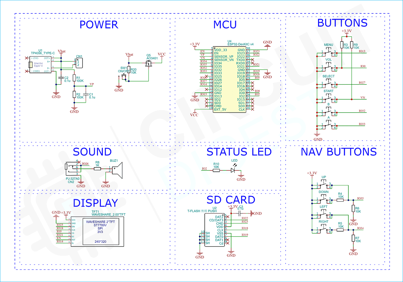
The complete circuit diagram of this ESP32 game console is displayed below.
The circuit is built around readily available off-the-shelf components. Connections are straightforward and easy to understand. The input supply is connected to the TP4056 module with a built-in protection circuit. If your battery already has a protection circuit built in, you can simply use the TP4056 module without the protection circuit. The battery is connected to the output of the TP4056 module. From there, the supply is connected to a high-side P-Channel MOSFET. By default, the gate of this MOSFET is pulled up to the VBAT level. When the small slide switch is switched on, the gate will be connected to the ground, and the MOSFET will be turned on. This simple circuitry will allow us to turn on and off the entire device using a tiny slide switch.
The power from the MOSFET is distributed to other components. The display is connected to the ESP32 Wrover kit using the SPI pins. The backlight brightness is controlled using the PWM from GPIO14. The SD card is also connected using the same SPI line. The sound is taken out from the GPIO26 and connected to a 3.5mm audio jack. You can either use the audio jack to connect a headphone, or you can use a buzzer with the audio jack switch terminal. An LED is connected to the GPIO2 to show the disk read status. Whenever the system is busy reading from the SD card, the LED will light up. All the switches are connected to various GPIO pins, and the state of these pins is monitored to detect a key press.
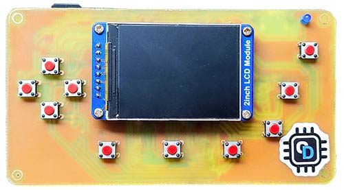
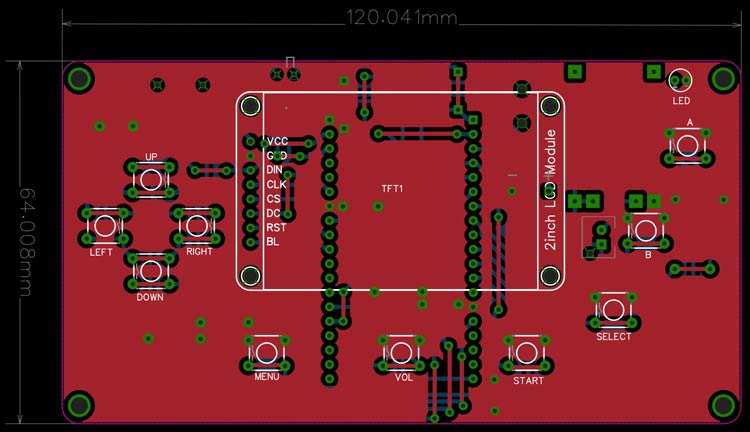
To make this DIY retro game console project easier, we designed a PCB for the project. The image below shows the dimensions of the PCB. It's a homemade etched PCB, and its necessary files can be downloaded from the GitHub link given at the end of this article. Here's how you make PCBs at home.
The image below shows the 2D representation of the PCB.
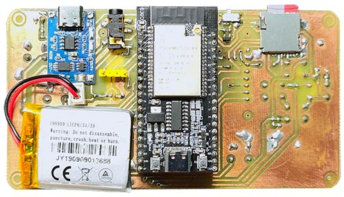
And the below image shows the 3D illustration of the same PCB. In the 3D model, you can see the placement of all the components.
Modified Firmware for ESP32 Retro Gaming
As mentioned earlier, the firmware used is a modified version of ducalex's retro-go firmware. The original firmware is coded to use with the ILI9341 display. Since we are using an IPS display with an ST7789V driver, we can’t use the original firmware. Thankfully, most of the display functions are somewhat similar for both the LCD driver chips. But we must change the display initialisation codes and the gamma settings. You can find the modified firmware source code in the following GitHub repo: Retro-go-ST7789. To use the firmware, you can either use the prebuilt image or you can build it yourself. The prebuilt image file can be found at the Circuit Digest GitHub repo linked at the end of this tutorial.
Nintendo: NES, SNES (slow), Gameboy, Gameboy Color, Game & Watch
Nintendo: NES, SNES (slow), Gameboy, Gameboy Color, Game & Watch
Sega: SG-1000, Master System, Mega Drive / Genesis, Game Gear
Sega: SG-1000, Master System, Mega Drive / Genesis, Game Gear
Coleco: Colecovision
Coleco: Colecovision
Others: DOOM (including mods!)
Others: DOOM (including mods!)
This gaming console built using ESP32 includes professional features such as:
Favorites and recently played
Favorites and recently played
GB color palettes, RTC adjust and save
GB color palettes, RTC adjust and save
NES color palettes, PAL roms, NSF support
NES color palettes, PAL roms, NSF support
More emulators and applications
More emulators and applications
Scaling and filtering options
Scaling and filtering options
Better performance and compatibility
Better performance and compatibility
Turbo Speed/Fast forward
Turbo Speed/Fast forward
Technologies used
Hardware components
- ESP32
- ESP8266
- Arduino
- DHT22
- Relay
- OLED
- NodeMCU
Software & tools
- Arduino IDE
- Blynk
- Firebase Console
- Node-RED
- MQTT Broker
What you get
- Working project / hardware kit, tested before delivery
- Complete source code with explanation
- Project demo and guidance for your viva
- Project report, PPT and IEEE paper support (on request)
Related IoT projects

DIY IoT Plant Watering System using Arduino
A remote plant-watering system that monitors soil moisture and lets you trigger a water pump from anywhere through the Blynk app, with LED-m...
View project
Build a smart mirror with an Arduino UNO Q
A wall-mounted smart mirror that shows the time, calendar, to-do list, room temperature/humidity and weather forecast behind a two-way glass...
View project
ESP32 Patient Health Monitor ECG SpO2 BPM Live Dashboard
Build a complete patient health monitoring system using ESP32 with AD8232 ECG sensor, MAX30102 pulse oximeter, BME280 and live web dashboard...
View project
IoT AC Energy Meter with PZEM-004T and ESP32 WebServer
Build an IoT-based AC energy meter using ESP32 and PZEM-004T to measure voltage, current, power, frequency and energy with live web dashboar...
View project