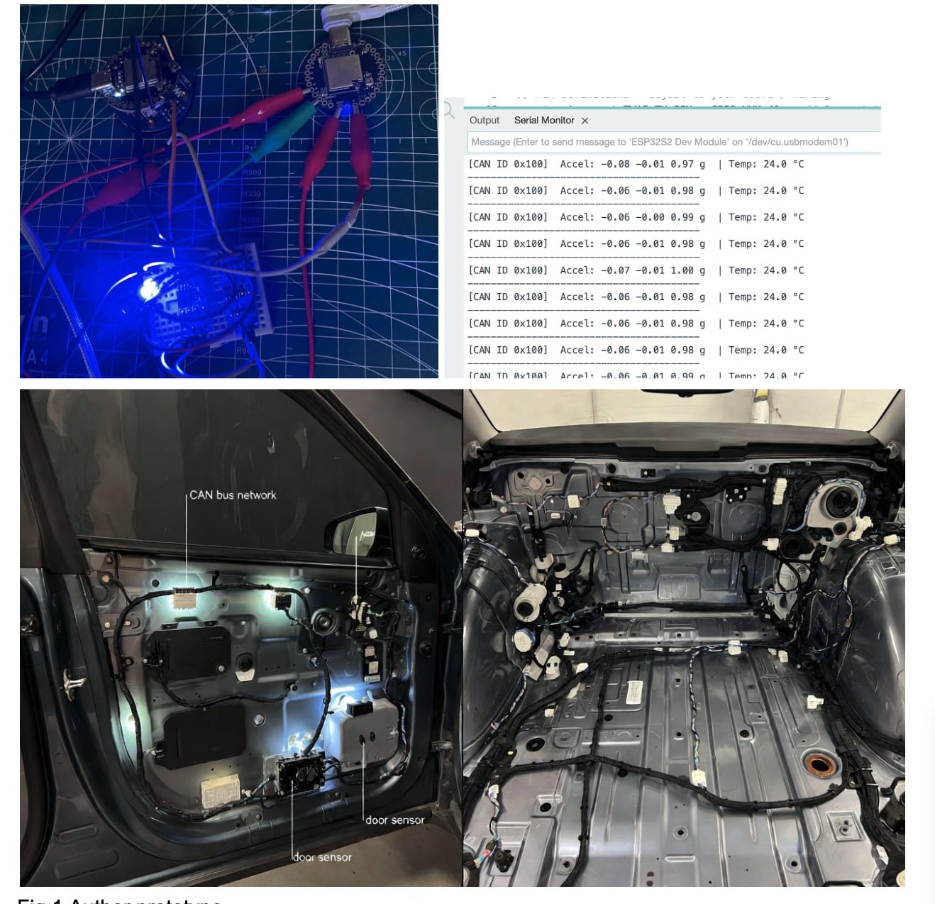
DIY CAN Bus Vehicle Sensor
Here we are designing a very small CAN network sensor that can be attached to any vehicle. It detects motion, accidents, and all vehicle activities in real time.
- Suitable forB.Tech IoT students
- Build time3-4 weeks
- LevelBeginner
- Available atAjvika Labs, Kakinada
About this project
Here we are designing a very small, tiny CAN network sensor that can be attached to any vehicle. It detects motion, accidents, and all vehicle activities in real time. It can also be modified to act like a black box for the vehicle, storing all activity logs. This is not just for cars, it can be used in ships, motorboats, drones, rockets, and almost any area where CAN bus is already used. It can be programmed to add more sensors and send their data to the CAN bus network. In the current design, we are using the IndusBoard Coin, which is super small (only about 3 cm) and has a built-in IMU, temperature sensor, and many other features, plus support for an internal CAN bus driver. Our system uses its internal IMU and sensors to detect the vehicle activity, orientation, and events. It can identify time, accidents, whether the vehicle rolled over, collisions, braking, speed, acceleration, deceleration, and sends all this data to the CAN bus network to the engine ECU or the vehicle main board. What is CAN Bus? Unlike many other communication peripherals, CAN Bus does not require separate wiring for each device. Instead, all electronic control units (ECUs) such as the engine controller, brakes, dashboard, and sensors are connected using just two twisted wires. These wires allow every ECU to listen and talk on the same network. In a multi-master configuration, all ECUs share the CAN Bus, meaning any ECU can take control of the bus at any time and broadcast messages, such as sensor data or control commands, to the entire system. Every ECU receives these messages and independently decides whether to process or ignore them based on the message identifier. The physical layer of the CAN Bus consists of only two twisted wires: CAN High and CAN Low. Twisting the pair helps cancel electromagnetic interference, ensuring reliable communication even in the electrically noisy environment of a vehicle. Data transmission works by varying the voltage levels on these two wires. When the bus is idle or transmitting a logic 1 (recessive state), both CAN High and CAN Low sit at approximately 2.5 V. When a node transmits a logic 0 (dominant state), CAN High rises to about 3.5 V while CAN Low drops to around 1.5 V, creating a 2-volt differential. OBD2 Port: Almost every car made after 1996 has an OBD2 port. It is a 16-pin connector usually under the dashboard on the driver side. Important CAN Bus pins: Pin 6 CAN High, Pin 14 CAN Low, Pin 16 Battery 12V, Pins 4 and 5 Ground. Most modern vehicles use CAN protocol on these pins at 500 kbps speed.
Technologies used
Project demo video
What you get
- Working project / hardware kit, tested before delivery
- Complete source code with explanation
- Project demo and guidance for your viva
- Project report, PPT and IEEE paper support (on request)
Delivery & Payment
Delivery takes a minimum of two weeks from the date your inquiry is confirmed.
Payment is in two parts:
• 50% advance to start the project
• Remaining 50% before delivery
Note:
• Documentation and PPT are not included by default
• If you need documentation/PPT, it can be arranged for extra time and cost
We'll confirm the exact timeline and cost with you after reviewing your requirements.
Related IoT projects

IoT
DIY IoT Plant Watering System using Arduino
A remote plant-watering system that monitors soil moisture and lets you trigger a water pump from anywhere through the Blynk app, with LED-m...
View project
IoT
Build a smart mirror with an Arduino UNO Q
A wall-mounted smart mirror that shows the time, calendar, to-do list, room temperature/humidity and weather forecast behind a two-way glass...
View project
IoT
ESP32 Patient Health Monitor ECG SpO2 BPM Live Dashboard
Build a complete patient health monitoring system using ESP32 with AD8232 ECG sensor, MAX30102 pulse oximeter, BME280 and live web dashboard...
View project
IoT
IoT AC Energy Meter with PZEM-004T and ESP32 WebServer
Build an IoT-based AC energy meter using ESP32 and PZEM-004T to measure voltage, current, power, frequency and energy with live web dashboar...
View project