


Designing and Controlling Quadruped Spider Robot with ESP32
In this robotic project, we will build Quadruped Spider Robot and controlling with ESP32. We will do programming this robot using Arduino IDE.
- Suitable forB.Tech IoT students
- Build time3-4 weeks
- LevelIntermediate
- Available atAjvika Labs, Kakinada
About this project
Nature has always been an incredible source of inspiration for technological advancements and engineers have sought to replicate the intricate mechanisms found in various animals. One such remarkable creation is the spider robot. It can also known as a quadruped robot due to its four legs. This innovative robotic project aims to emulate the locomotion and behavior of spiders. Learn more using our previously built robotic projects.
Spider robot is a four-legged walking robot which is inspired by or a bionic replica of spider that uses their legs for movement. The legs are arranged in a way that allows them to move in a variety of ways, including walking, running, and climbing. An integral component of this project is the integration of the ESP32 microcontroller, which enables wireless control and advanced motion coordination. The ESP32 serves as an ideal platform for the spider robot, enhancing its agility, versatility, and capacity to navigate complex terrains effectively. With their exceptional agility, versatility, and ability to traverse complex terrains, spider robots hold immense potential in various fields, including search and rescue missions, exploration, and even household assistance.
Mechanism of Spider Robot
The mechanism of a spider robot involves several key components and principles that enable its locomotion and functionality.
Spider robots belong to the category of legged robots, which are typically more intricate than wheeled robots. Legged robots excel in traversing challenging terrains compared to wheeled robots. While wheeled robots usually have DC motors whereas legged robots generally have servo motors.
One fundamental distinction between wheeled and legged robots lies in their degrees of freedom (DOF). Wheeled robots only have one degree of freedom whereas a legged robot has a more complex motion.
Degrees of freedom (DOF) of a body are defined by the number of parameters it takes to define the position of that same body. In the case of our spider robot have 2 servo motors in each of its legs to give out 2 different directions of motion. This means that the degree of freedom (DOF) for one leg is 2. So the total degrees of freedom (DOF) of spider robot is 8.
This project might not be very complex in terms of the wiring and the assembly, but it is incredibly complex to understand the kinematics behind the motion of the quadruped spider robot.
To achieving controlled movement, the robot has to perform a different number of poses that collectively generate a single motion. It can be done by implementing crawl gait (pattern of movement) in which one leg will be in air and remaining three legs should be in contact with the ground while moving. Typically, to take one step forward, the robot undergoes 6 distinct poses.
Gait refers to the specific pattern of leg movement required to propel the body towards a desired destination. In the case of quadruped robots, the gait involves lifting one leg at a time while the remaining three legs form a supportive tripod. This coordinated movement ensures stability and efficient locomotion.
To achieve quadruped gait, the key is to determine when and at what position each leg should move. This process is known as inverse kinematics. Inverse kinematics enables us to calculate the necessary values for the servo motors controlling the legs, allowing precise positioning of the legs to achieve the desired gait pattern.
Inverse kinematics plays a crucial role in the smooth execution of the quadruped gait. By providing the necessary instructions to the servo motors, the robot's legs can be accurately moved to their intended positions. This helps in maintaining balance and achieving efficient locomotion
The above diagram illustrates the forward quadruped gait, showcasing the sequence of leg movements required for the robot to move forward effectively. The dotted line shows that the foot has been lifted.
To ensure the stability of the robot, it is crucial for the center of mass (COM) to remain within the support polygon. The support polygon refers to an imaginary polygon within which, if the COM is located, the robot can maintain its balance. However, if the COM shifts outside of the support polygon, the robot becomes unstable and may tip over. The concept is depicted in the figure below, where the robot remains balanced as long as the COM resides inside the support polygon. It serves as a critical principle for maintaining stability and preventing falls in the robot's operation.
Components Required for Spider Robot
ESP32 microcontroller
ESP32 microcontroller
SG90 plastic gear servo motor - 8pcs
SG90 plastic gear servo motor - 8pcs
LM2596 DC-DC Buck converter
LM2596 DC-DC Buck converter
Breadboard or PCB (Printed Circuit Board)
Breadboard or PCB (Printed Circuit Board)
Screws, nuts, spacers
Screws, nuts, spacers
Spider Robot Laser Cutting Files
Auadruped Spider robot Acrylic Body
We have designed the Quadruped Spider Robot Acrylic parts using SolidWorks. The .dxf files, you can find on the above link. If you want to make any changes, you can also find .svg file. These pieces are also readily available on many E-commerce websites, just search \"Quadruped Spider Robot parts\" on google and you will find many links.
Assembly of Spider Robot
Before starting the assembly, we need to adjust the angle adjustment of the servo motors. Otherwise, your robot will not work properly.
To begin, attach the Servo Arm to the servo by carefully aligning and securing it in place. We can manually calibrate and adjust the servo motor angle but some time manually calibration is not accurate or may not be possible. So you can calibrate your servo motors using the provided code #1. Refer to the circuit diagram mentioned below and connect your servo motors to pins 21, 19, 33, 25, 27, 14, 12, and 13 accordingly. Upload the provided code #1 to your ESP32, which will facilitate the calibration process. Failing to execute this step may result in unstable performance of your robot.
By ensuring proper alignment and calibration of the servos, you lay the foundation for a stable and well-functioning robot.
After done with servo adjustments, you can pass to Leg Assembly stages.
Step 1 : Take a servo single arm and place it on the pedestal pivot plate. Insert the servo mounting screw into the servo single arm from the rear side of the leg-up pivot plate. Tighten the screw until the servo single arm is securely attached to the pivot plate.
Step 2 : Now, attach another servo single arm to the standing servo arm. To do this, insert a servo mounting screw from the back of the leg servo arm and fasten it into the servo single arm. Make sure the connection is firm and stable.
Step 3 : Moving on, connect the leg parallel joint to the leg piece using an M3x10mm screw and an M3 fiber nut. Double-check the tightness of the screw to ensure the joint is firmly joined to the leg piece.
Step 4 : Next, attach the leg piece to the leg servo arm using an M3x10mm screw and an M3 fiber nut.
Step 5 : Insert another servo into the servo holder.
Step 6 : Place the top end of the second servo into the pedestal servo slot.
Step 7 : Fasten the servo holder to the leg servo socket using two M3x12mm screws and two M3 fiber nuts.
Step 8 : Now, connect a leg parallel plate to the other end of the leg using an M3x10mm screw and an M3 fiber nut.
Step 9 : With both servos in the center position and the leg parallel joint horizontally aligned, attach the leg servo arm to the first servo using the supplied servo arm screw.
Step 10 : Finally, join the Leg Assembly, which was completed in the previous steps, to the Leg Bottom Pivot Plate using two M3x10mm screws and two M3 nuts.
The Leg Assembly stage may have been challenging, but once these steps are completed, the remaining process becomes more manageable. If you have successfully finished these stages, let's proceed to the Body Assembly part.
In this stage, you should be careful with the numbers. Schematics is explained according to the part numbers, so that you should read the lists that we created, before the assembly.
Part List of Schema 1 & 2 :
Step 1 : Begin the assembly by attaching the four stem spacers to the stem bottom plate. Use four M3x10mm screws and four M3 flat nuts to secure the spacers firmly in place.
Step 2 : Take the four servos and position them on top of the chassis top plate, making sure they are correctly aligned.
Step 3 : For each servo, attach a servo holder on top. Align the holder properly and secure it in place.
Step 4 : Fasten each servo holder to the chassis top plate using M3x12mm screws and M3 fiber nuts. Ensure they are tightened securely
Step 5 : Now, proceed to attach each leg piece to the stem bottom plate. Use an M3x10mm screw and an M3 fiber nut for each leg piece. Be cautious not to over-tighten the screws, as it may lead to servo malfunctions.
Step 6 : Bring together the body bottom plate and the body top plate. Use four M3x10mm screws and M3 nuts to firmly connect these two components.
Step 7 : With the servos and leg pieces in place, carefully rotate each leg to a 45-degree angle as shown in the instructions. Install the leg upper pivot plate and secure it to each pivot servo and leg using two M3x10mm screws and two M3 nuts for each leg.
Step 8 : Finally, secure the servo single arm to its respective servo using a servo screw, making sure it is firmly attached..
After assembly, it will look like this:
ESP32 Circuit Diagram for Quadruped Spider Robot (8 Servo Motors)
This circuit diagram illustrates the integration of 12 servo motors, enabling locomotion movement in all directions for the robot.
The robot consists of four legs, with each leg connected to two servo motors. One servo is responsible for axis rotation (known as the pivot servo), while the other servo controls the lifting motion of the leg (known as the lift servo).
To achieve coordinated movement, the servo motors are connected in a specific sequence or order. The precise order and connections depend on the desired gait pattern and the specific control algorithm being employed. By controlling the movement of these servo motors in a synchronized manner, the robot can achieve stable and coordinated locomotion.
ESP32 and Servo Motors :
Technologies used
Hardware components
- ESP32
- ESP8266
- Arduino
- DHT22
- Relay
- OLED
- NodeMCU
Software & tools
- Arduino IDE
- Blynk
- Firebase Console
- Node-RED
- MQTT Broker
Project demo video
What you get
- Working project / hardware kit, tested before delivery
- Complete source code with explanation
- Project demo and guidance for your viva
- Project report, PPT and IEEE paper support (on request)
Delivery & Payment
Delivery takes a minimum of two weeks from the date your inquiry is confirmed.
Payment is in two parts:
• 50% advance to start the project
• Remaining 50% before delivery
Note:
• Documentation and PPT are not included by default
• If you need documentation/PPT, it can be arranged for extra time and cost
We'll confirm the exact timeline and cost with you after reviewing your requirements.
Related IoT projects

IoT
DIY IoT Plant Watering System using Arduino
A remote plant-watering system that monitors soil moisture and lets you trigger a water pump from anywhere through the Blynk app, with LED-m...
View project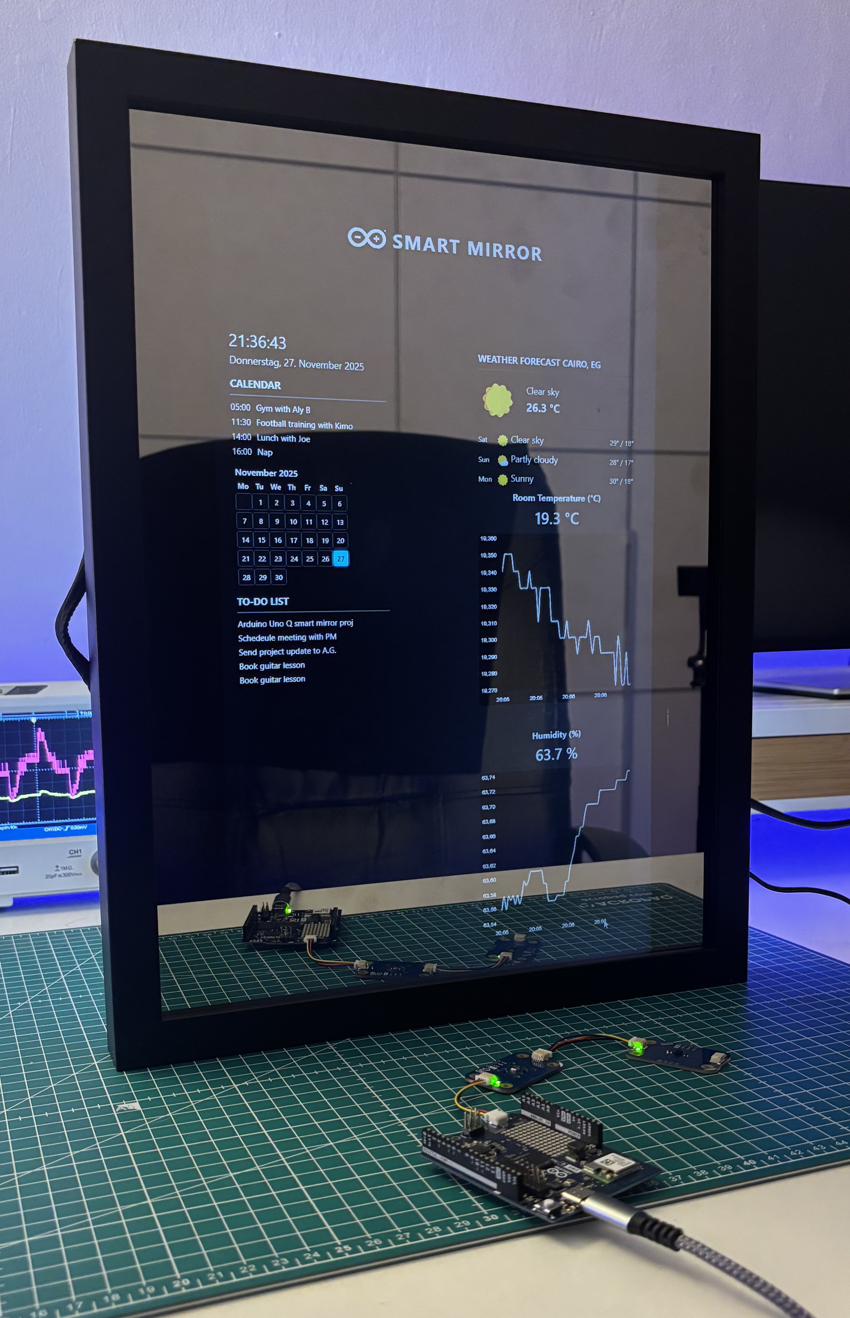
IoT
Build a smart mirror with an Arduino UNO Q
A wall-mounted smart mirror that shows the time, calendar, to-do list, room temperature/humidity and weather forecast behind a two-way glass...
View project
IoT
ESP32 Patient Health Monitor ECG SpO2 BPM Live Dashboard
Build a complete patient health monitoring system using ESP32 with AD8232 ECG sensor, MAX30102 pulse oximeter, BME280 and live web dashboard...
View project
IoT
IoT AC Energy Meter with PZEM-004T and ESP32 WebServer
Build an IoT-based AC energy meter using ESP32 and PZEM-004T to measure voltage, current, power, frequency and energy with live web dashboar...
View project