



Controlling Light using Touch Sensor and 8051 Microcontroller
What is a Capacitive Touch Sensor? In this project will interface a capacitive touch sensor module with 8051 microcontroller AT89S52.
- Suitable forB.Tech IoT students
- Build time3-4 weeks
- LevelIntermediate
- Available atAjvika Labs, Kakinada
About this project
In modern electronics world, touch input is used almost everywhere, whether it can be a mobile phone or an LCD monitor switch. Capacitive touch is the widely used in the touch sensor segment and we previously used capacitive touch with a Raspberry Pi. Here in this project, we will interface touch sensor with 8051 microcontroller AT89S52. If you are new to 8051 microcontoller then you can start with LED blinking with 8051.
What is a Capacitive Touch Sensor?
Capacitive touch works on the electrostatic charge that is available on our body. The screen is already charged with electric field. When we touch the screen a close circuit forms due to electrostatic charge that flows through our body. Further, software decides the location and the action to be performed. Capacitive touch screen won’t work with hand gloves because there won’t be any conduction between the finger(s) and the screen.
Touch Sensor used in this project
The touch sensor used in this project is a capacitive touch sensor module and the sensor driver is based on the driver IC TTP223. The operating voltage of the IC TTP23 is 2.0V to 5.5V and the current consumption of the touch sensor is very low. Due to the inexpensive, low current consumption, and easy to integrate support, the touch sensor with TTP223 is widely popular in its a segment.
In the above image, both sides of the sensor are shown where the pinout diagram is clearly visible. It also has a solder jumper which can be used to reconfigure the sensor in respect of the output. The jumper is A and B. Default configuration or in the default state of the solder jumper, the output changes from low to high when the sensor is being touched. However, when the jumper is set and the sensor is reconfigured, the output changes its state when the touch sensor detects the touch. The sensitivity of the touch sensor can be also configured by changing the capacitor. For the detailed info, the datasheet of the TTP 223 is very useful.
Below chart is showing different outputs at different jumper settings-
For this project, the sensor will be used in default configuration which is available on factory release condition. In this project, the touch sensor will be used to control a AC light bulb using AT89S52 microcontroller.
A relay is interfaced with the 8051 microcontroller. The pinout of the relay can be seen in the below image-
NO is normally open and NC is normally connected. L1 and L2 are the two terminals of the Relay coil. When the Voltage is not applied, the relay is turned off and the POLE gets connected with the NC pin. When the voltage is applied across the coil terminals, L1 and L2 of relay gets turned ON and the POLE gets connected with NO. Therefore, connection between POLE and NO can be switched ON or OFF by changing the operation state of the Relay.
AT89S52 8051 Microcontroller
Standard Cubic Relay - 5V
33pF capacitors - 2pcs
4.7k resistor - 1 pc
Light Bulb With Bulb Holder
5V power supply, A phone charger can work.
Lots of jumper wires or berg wires.
AT89S52 programming environment with Programmer Kit and IDE with compiler
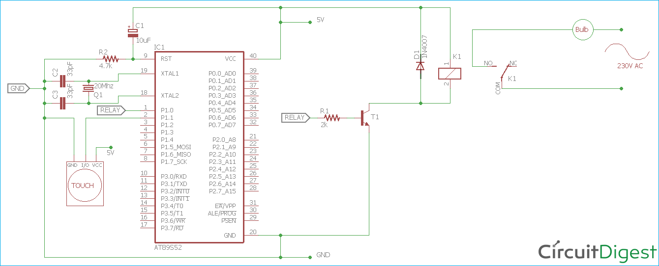
The schematic for controlling light using touch sensor and 8051 is given below image,
The transistor is used to switch on or off the Relay. The touch sensor is connected with the AT89S52 microcontroller unit. The circuit is constructed using a breadboard.
Programming Atmega AT89S52 Microcontroller
The below code lines are used for integrating the Relay and the Touch Sensor with 8051 Microcontroller. REGX52 is the header file for the AT89S52 microcontroller unit. A delay function is also declared.
The touch and relay are initialized as 0. The touch sensor changes the logic 0 to 1. If the statement is true when the touch sensor is activated and due to this, the state of the Relay gets changed. However, to detect the touch accurately, a debounce delay is used.
Below, the delay function is written. The function takes input in milli-seconds format and generates delay using two for loops. This delay is not much accurate but is acceptable and it mostly depends on the clock cycle timing.
This Touch controlled Light circuit is tested on the breadboard with a low power bulb connected to it. The complete sketch with a demonstration video is attached below. You can check more home automation projects here.
Complete Project Code
What is a Capacitive Touch Sensor?
Capacitive touch works on the electrostatic charge that is available on our body. The screen is already charged with electric field. When we touch the screen a close circuit forms due to electrostatic charge that flows through our body. Further, software decides the location and the action to be performed. Capacitive touch screen won’t work with hand gloves because there won’t be any conduction between the finger(s) and the screen.
Touch Sensor used in this project
The touch sensor used in this project is a capacitive touch sensor module and the sensor driver is based on the driver IC TTP223. The operating voltage of the IC TTP23 is 2.0V to 5.5V and the current consumption of the touch sensor is very low. Due to the inexpensive, low current consumption, and easy to integrate support, the touch sensor with TTP223 is widely popular in its a segment.
In the above image, both sides of the sensor are shown where the pinout diagram is clearly visible. It also has a solder jumper which can be used to reconfigure the sensor in respect of the output. The jumper is A and B. Default configuration or in the default state of the solder jumper, the output changes from low to high when the sensor is being touched. However, when the jumper is set and the sensor is reconfigured, the output changes its state when the touch sensor detects the touch. The sensitivity of the touch sensor can be also configured by changing the capacitor. For the detailed info, the datasheet of the TTP 223 is very useful.
Below chart is showing different outputs at different jumper settings-
For this project, the sensor will be used in default configuration which is available on factory release condition. In this project, the touch sensor will be used to control a AC light bulb using AT89S52 microcontroller.
A relay is interfaced with the 8051 microcontroller. The pinout of the relay can be seen in the below image-
NO is normally open and NC is normally connected. L1 and L2 are the two terminals of the Relay coil. When the Voltage is not applied, the relay is turned off and the POLE gets connected with the NC pin. When the voltage is applied across the coil terminals, L1 and L2 of relay gets turned ON and the POLE gets connected with NO. Therefore, connection between POLE and NO can be switched ON or OFF by changing the operation state of the Relay.
AT89S52 8051 Microcontroller
Standard Cubic Relay - 5V
33pF capacitors - 2pcs
4.7k resistor - 1 pc
Light Bulb With Bulb Holder
5V power supply, A phone charger can work.
Lots of jumper wires or berg wires.
AT89S52 programming environment with Programmer Kit and IDE with compiler
The schematic for controlling light using touch sensor and 8051 is given below image,
The transistor is used to switch on or off the Relay. The touch sensor is connected with the AT89S52 microcontroller unit. The circuit is constructed using a breadboard.
Programming Atmega AT89S52 Microcontroller
The below code lines are used for integrating the Relay and the Touch Sensor with 8051 Microcontroller. REGX52 is the header file for the AT89S52 microcontroller unit. A delay function is also declared.
The touch and relay are initialized as 0. The touch sensor changes the logic 0 to 1. If the statement is true when the touch sensor is activated and due to this, the state of the Relay gets changed. However, to detect the touch accurately, a debounce delay is used.
Below, the delay function is written. The function takes input in milli-seconds format and generates delay using two for loops. This delay is not much accurate but is acceptable and it mostly depends on the clock cycle timing.
This Touch controlled Light circuit is tested on the breadboard with a low power bulb connected to it. The complete sketch with a demonstration video is attached below. You can check more home automation projects here.
Complete Project Code
Technologies used
Hardware components
- ESP32
- ESP8266
- Arduino
- DHT22
- Relay
- OLED
- NodeMCU
Software & tools
- Arduino IDE
- Blynk
- Firebase Console
- Node-RED
- MQTT Broker
Project demo video
What you get
- Working project / hardware kit, tested before delivery
- Complete source code with explanation
- Project demo and guidance for your viva
- Project report, PPT and IEEE paper support (on request)
Delivery & Payment
Delivery takes a minimum of two weeks from the date your inquiry is confirmed.
Payment is in two parts:
• 50% advance to start the project
• Remaining 50% before delivery
Note:
• Documentation and PPT are not included by default
• If you need documentation/PPT, it can be arranged for extra time and cost
We'll confirm the exact timeline and cost with you after reviewing your requirements.
Related IoT projects

IoT
DIY IoT Plant Watering System using Arduino
A remote plant-watering system that monitors soil moisture and lets you trigger a water pump from anywhere through the Blynk app, with LED-m...
View project
IoT
Build a smart mirror with an Arduino UNO Q
A wall-mounted smart mirror that shows the time, calendar, to-do list, room temperature/humidity and weather forecast behind a two-way glass...
View project
IoT
ESP32 Patient Health Monitor ECG SpO2 BPM Live Dashboard
Build a complete patient health monitoring system using ESP32 with AD8232 ECG sensor, MAX30102 pulse oximeter, BME280 and live web dashboard...
View project
IoT
IoT AC Energy Meter with PZEM-004T and ESP32 WebServer
Build an IoT-based AC energy meter using ESP32 and PZEM-004T to measure voltage, current, power, frequency and energy with live web dashboar...
View project