

Building a Simple ESP32 LED Webserver: Step-by-Step Tutorial
In this blog post, we'll explore how to build an ESP32 LED web server from scratch. We'll go through the steps of setting up the ESP32, connecting the LEDs, and creating a web interface to control them.
- Suitable forB.Tech IoT students
- Build time3-4 weeks
- LevelIntermediate
- Available atAjvika Labs, Kakinada
About this project
In the Internet, all the websites are hosted on a computer and this computer is called a server. Since this particular server is used to serve web pages and web requests, we call it a web server. Instead of using a computer, we can also use an ESP32 to respond to web requests, thanks to the ESP32’s built-in WiFi. The ESP32 can not only respond to requests, but also serve small web pages, that were either hard coded to the code or stored in flash storage of an SD card.
In this blog post, we'll explore how to build an ESP32 LED web server from scratch. We'll go through the steps of setting up the ESP32, connecting the LEDs, and creating a web interface to control them. Whether you're a seasoned maker or just starting out with IoT projects, this tutorial will help you take your skills to the next level.
You can also take a look at a few other ESP32 Projects that we made and also check our previously built webservers using Raspberry Pi, NodeMCU and other microcontrollers:
How to Build NodeMCU Webserver and control an LED from a Webpage
Getting started with Node.js and Raspberry Pi: Controlling an LED with Node.js Webserver
AJAX with ESP8266: Dynamic Web Page Update Without Reloading
Connecting ESP8266 with STM32F103C8: Creating a Webserver
ESP8266 Interfacing with ARM7-LPC2148- Creating a Webserver to control an LED
Now, Let’s get a brief idea lets lern how to make an LED On/Off using ESP32 Webserver
Connecting LEDs on GPIO12 and GPIO14 on ESP32 so that you can control them
Connecting LEDs on GPIO12 and GPIO14 on ESP32 so that you can control them
After the coding is done. Try to access the control webpage by inputting the IP address of esp32 in the browser
After the coding is done. Try to access the control webpage by inputting the IP address of esp32 in the browser
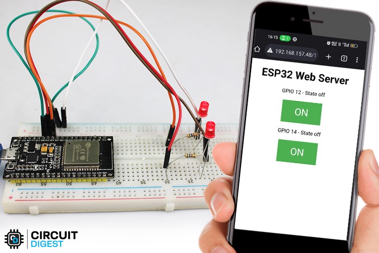
Clicking the buttons on the webpage to turn the LED “ON” or “OFF”
Clicking the buttons on the webpage to turn the LED “ON” or “OFF”
Materials Required to Build a LED Control Webserver using ESP32
The components we require to make this project are: -
ESP32 Development Board - this is the main component that will be used to control the LED lights through the webserver.
ESP32 Development Board - this is the main component that will be used to control the LED lights through the webserver.
LED Lights - you can use any type of LED depending on your project requirements. We have used 2x 5mm LEDs for this project.
LED Lights - you can use any type of LED depending on your project requirements. We have used 2x 5mm LEDs for this project.
Breadboard - this will be used to connect the LED lights to the ESP32 microcontroller.
Breadboard - this will be used to connect the LED lights to the ESP32 microcontroller.
Jumper wires - these will be used to connect the breadboard to the ESP32 microcontroller and the LED lights.
Jumper wires - these will be used to connect the breadboard to the ESP32 microcontroller and the LED lights.
USB Cable - to connect the ESP32 Development Board to your computer for programming.
USB Cable - to connect the ESP32 Development Board to your computer for programming.
Computer - to program and upload the code to the ESP32 Development Board.
Computer - to program and upload the code to the ESP32 Development Board.
Resistor - to limit the current going through the LED lights and prevent them from burning out.
Resistor - to limit the current going through the LED lights and prevent them from burning out.
Working of ESP32 LED WebServer
The project works by creating a web server on the ESP32 microcontroller that serves a web page to a client device, such as a computer or mobile phone, over Wi-Fi. The web page contains controls that allow you to turn the LED lights on or off.
Here's a step-by-step breakdown of how the ESP32 LED webserver project works:
The ESP32 microcontroller is connected to the LED lights and programmed to serve as a web server.
The ESP32 microcontroller is connected to the LED lights and programmed to serve as a web server.
The web server code is uploaded to the ESP32 using the Arduino IDE or other programming tools.
The web server code is uploaded to the ESP32 using the Arduino IDE or other programming tools.
The ESP32 is connected to a Wi-Fi network, allowing it to communicate with client devices over the network.
The ESP32 is connected to a Wi-Fi network, allowing it to communicate with client devices over the network.
When a client device connects to the ESP32's IP address, the web server code serves a web page to the client device's web browser.
When a client device connects to the ESP32's IP address, the web server code serves a web page to the client device's web browser.
The web page contains controls for the LED lights, allowing the user to turn them on or off.
The web page contains controls for the LED lights, allowing the user to turn them on or off.
When the user interacts with the controls on the web page, the ESP32 microcontroller receives the command and adjusts the LED lights accordingly.
When the user interacts with the controls on the web page, the ESP32 microcontroller receives the command and adjusts the LED lights accordingly.
The ESP32 sends a response back to the client device, updating the web page with the current state of the LED lights.
The ESP32 sends a response back to the client device, updating the web page with the current state of the LED lights.
Circuit Diagram of ESP32 LED WebServer
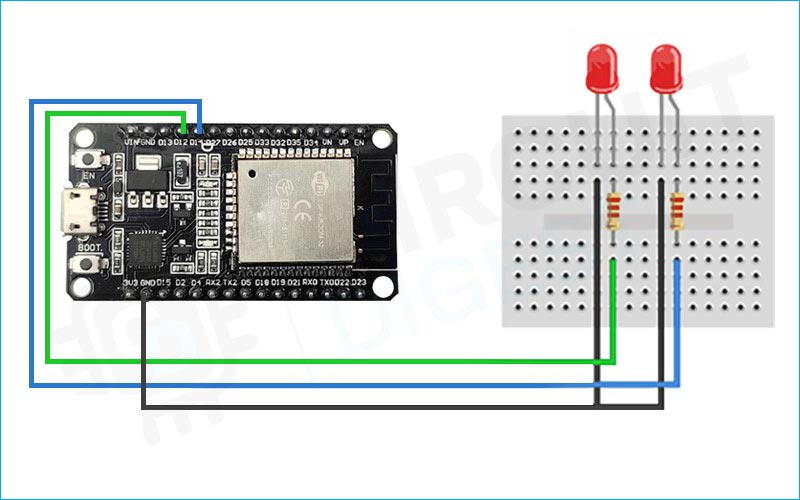
Below is the circuit diagram to control an LED using ESP32 based webserver :
The ESP32 microcontroller has many GPIO pins that can be used for interfacing with external devices, such as LED lights. In this example, we will interface the ESP32 with two LED lights connected to GPIO pins 12 and 14.
Here's how to interface the ESP32 with two LED lights:
Connect one end of a 220-ohm resistor to GPIO pin 12 on the ESP32, and connect the other end of the resistor to the positive (anode) leg of one LED light.
Connect the negative (cathode) leg of the LED light to the ground (GND) on the ESP32.
Repeat steps 1 and 2 for GPIO pin 14 and the other LED light.
You can also use the ESP32 Ethernet webserver for the same, in which case you will need an ethernet shield for ESP32 board and minor changes with the code.
Installing the ESP32 board on the Arduino IDE
The Arduino IDE provides a user-friendly interface for beginners and advanced users alike, allowing you to write and upload code to the ESP32 without requiring advanced knowledge of programming languages.
Here’s an in-depth tutorial that you can follow for this - Getting Started with ESP32 using Arduino IDE - Blink LED
Technologies used
Hardware components
- ESP32
- ESP8266
- Arduino
- DHT22
- Relay
- OLED
- NodeMCU
Software & tools
- Arduino IDE
- Blynk
- Firebase Console
- Node-RED
- MQTT Broker
Project demo video
What you get
- Working project / hardware kit, tested before delivery
- Complete source code with explanation
- Project demo and guidance for your viva
- Project report, PPT and IEEE paper support (on request)
Related IoT projects

DIY IoT Plant Watering System using Arduino
A remote plant-watering system that monitors soil moisture and lets you trigger a water pump from anywhere through the Blynk app, with LED-m...
View project
Build a smart mirror with an Arduino UNO Q
A wall-mounted smart mirror that shows the time, calendar, to-do list, room temperature/humidity and weather forecast behind a two-way glass...
View project
ESP32 Patient Health Monitor ECG SpO2 BPM Live Dashboard
Build a complete patient health monitoring system using ESP32 with AD8232 ECG sensor, MAX30102 pulse oximeter, BME280 and live web dashboard...
View project
IoT AC Energy Meter with PZEM-004T and ESP32 WebServer
Build an IoT-based AC energy meter using ESP32 and PZEM-004T to measure voltage, current, power, frequency and energy with live web dashboar...
View project