Battery Powered Attendance system using Face Recognition on ESP32-CAM Board
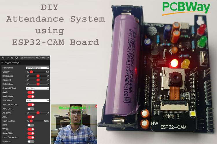
In this tutorial, we are going to build a ESP32-CAM development board that greatly simplifies working with the ESP-32. This development board features an integrated power supply with 5-volt and 3.3-volt output powered by a 18650 cell.
- Suitable forB.Tech IoT students
- Build time3-4 weeks
- LevelIntermediate
- Available atAjvika Labs, Kakinada
About this project
Access to all ESP32-CAM GPIO pins through both male and female connectors.
Multiple connector pins for +5-volts, +3.3-volts, and Ground.
Dedicated LEDs for indicating power and network connectivity.
Powered with a 18650 cell and comes with a charger and booster circuit.
This board can be directly mounted on a wall for applications like Face Recognition, Motion detection, etc.
IO0 Jumper for Programming Mode.
To test this ESP32-CAM development board we are going to build a Face Recognition-based Attendance system. It uses the CameraWebServer code from the ESP board for face recognition. Upon recognizing the face, the face ID with the name associated with it will be sent to Google Sheets. You can also check our previous ESP32 CAM board projects where we used ESP32-CAM for building a Face Recognition Based Door Lock.
Components Required for Building ESP32-CAM Development Board
TP4056 Li-Ion Battery Charger IC
FP6291 Boost Converter IC
Micro USB 2.0 B type 5 Pin Connector
7× Resistor (2×1k, 1.2k, 6k, 51k, 100ohm, 48k)
8× Capacitor (2×0.1µf, 4×10µf, 2×20µf)
1× Diode (1N5388BRLG)
AMS1117 3.3V Voltage Regulator
ESP32-CAM Development Board Circuit Diagram
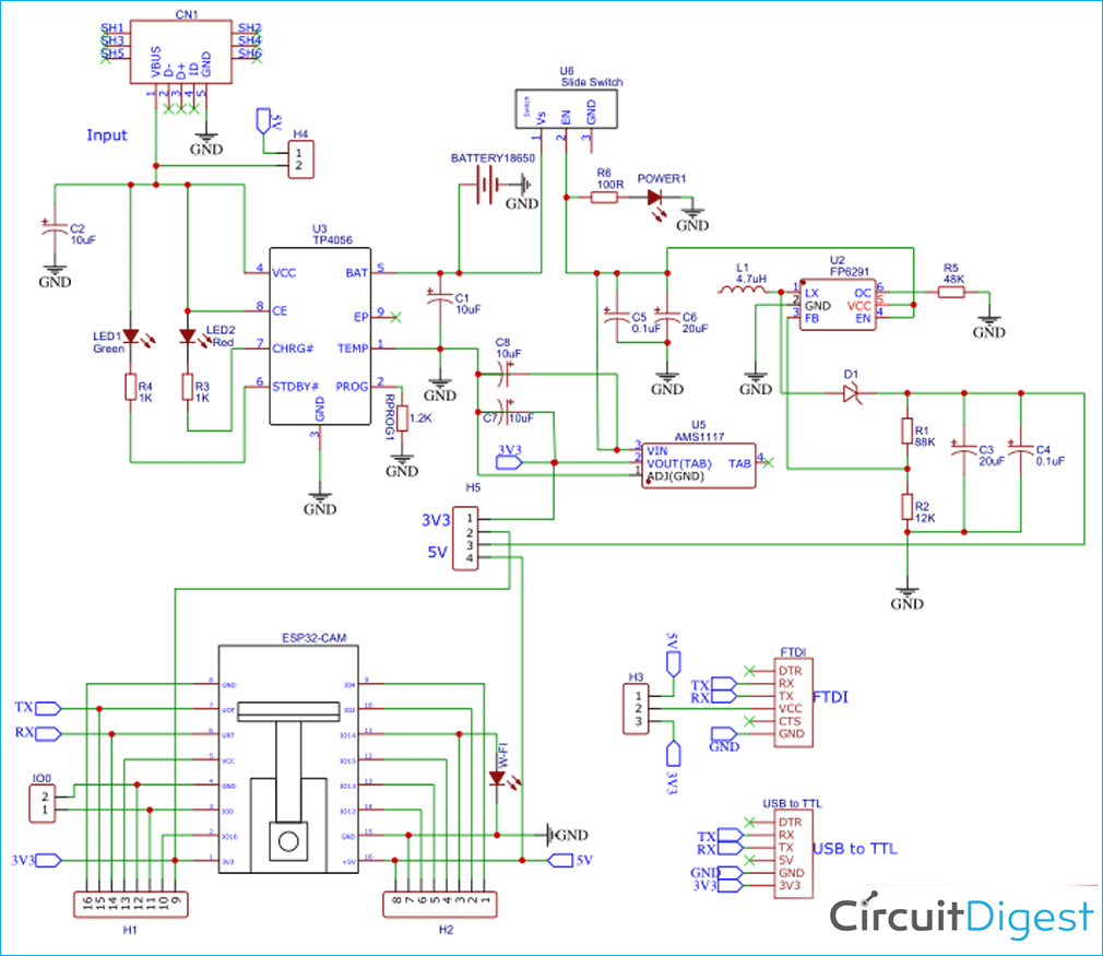
The circuit diagram for ESP32-CAM Board is given above. This circuit has three main parts, one is the battery charging circuit, the second is DC to DC boost converter circuit and the third is the ESP32-CAM part. The Booster part is used to boost the battery voltage from 3.7v to 4.5v-6v. Here in this circuit, a Micro USB 2.0 B type 5 Pin Connector is on the Charger side. The complete working of the circuit can also be found in the video at the bottom of this page.
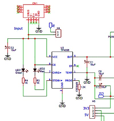
The battery charger circuit is designed around a dedicated lithium-ion battery charger TP4056 IC. TP4056 is a complete constant-current/constant-voltage linear charger for single-cell Lithium-ion batteries. Its SOP package and low external component count make the TP4056 ideally suited for portable applications. This IC handles the Battery charging operation by processing the 5V DC input supply received through the Micro USB socket. The LEDs connected with it indicate the charging status.
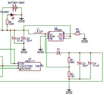
The DC-DC Boost Converter Circuit is designed using the DC-DC Boost Converter FP6291 IC. This 1 MHz DC-DC Step-Up Boost IC Can be used in the application, for example, getting stable 5V from 3V battery. The Boost Converter circuit gets the input supply through battery terminals (+ and -) is processed by FP6291 IC to give a stable 5V DC supply via the standard USB socket at its output.
ESP32-CAM Programming Circuit
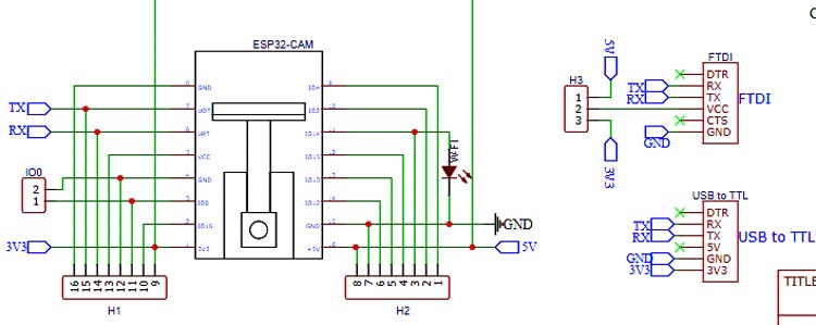
This section of the circuit consists of an ESP32-CAM board with one slot for FTDI board and another slot for USB to TTL converter so that we can directly plug any of the board and program the ESP32-CAM board directly.
Fabricating PCB for ESP32-CAM Development Board
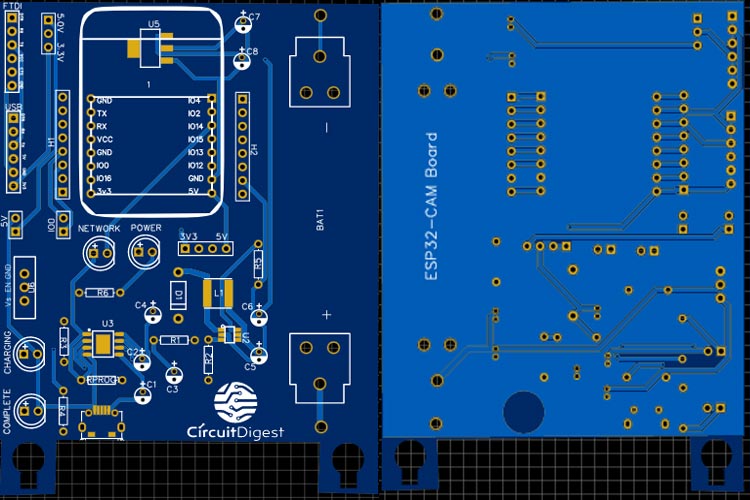
Now that we have the schematic, and we can proceed with laying out the PCB for the Ultrasonic range finder using ATtiny85. You can design the PCB using any PCB software of your choice. Below are the 3D model views of the top layer and bottom layer of the ESP32-CAM Development Board:
While designing the circuits and PCBs, you can also make your circuit, and PCB designs public so that other users can copy or edit them and can take benefit from your work. We have also made this ESP32-CAM Development Board PCB design file and GERBER file public, check the link given below:
Ordering PCB from PCBWay
Now after finalizing the design, you can proceed with ordering the PCB:
Step 2: Proceed by clicking on the ‘Quote Now’ button. You will be taken to a page to set a few additional parameters like the Board type, Layers, Material for PCB, Thickness, and More, most of them are selected by default, if you are opting for any specific parameters, you can select it in here.
Step 3: The final step is to upload the Gerber file and proceed with the payment. To make sure the process is smooth, PCBWAY verifies if your Gerber file is valid before proceeding with the payment. This way, you can be sure that your PCB is fabrication friendly and will reach you as committed.
Assembling the ESP32-CAM Development Board PCB
After a few days, we received our PCB in a neat package and the PCB quality was good as always. The top layer and the bottom layer of the board are shown below:
After making sure the tracks and footprints were correct. I proceeded with assembling the PCB. The completely soldered board looks like the below:
Setting-Up IFTTT for Sending Attendance Data to Google Sheets
As mentioned earlier attendance data received from ESP32-CAM will be sent to Google Sheets. For that, we are going to use IFTTT applets. This applet will get the data from ESP32-CAM using webhooks and then update it on Google Sheets.
First login to IFTTT and search for ‘Webhooks’.
Now to get the Private key, click on ‘Documentation’. Copy this key somewhere, it will be used in the code.
As we have the private key, we will create an applet using Webhooks and Google Sheets services. To create an applet, click on ‘Create’ in the top right corner.
Now in the next window, select If This Then That.
In the ‘This’ field we will use webhooks to get the web requests from the ESP32-CAM Board.
Now select ‘Receive a Web Request’ trigger and then enter the event name as attendance and then click on ‘Create Trigger.’
After this, click on ‘Then That’, search for ‘Google Sheets’ and select the Google Sheets icon.
Then in the next step select the “Add a row to spreadsheet” action.
After that, fill in the action fields. Give the spreadsheet a name, select a Google Drive folder path, and leave the \"Formatted row\" as default. If you leave the drive folder path blank, IFTTT will save the spreadsheet in a folder called \"IFTTT\" in your Google Drive folder. Finally, select “Create action” from the drop-down menu.
Programming ESP32-CAM for Student Attendance System
We explained Face Recognition with ESP32-CAM in the previous article; here we will modify the same code for marking attendance according to recognized face. The complete code is divided into three parts. One is the main code for the camera and attendance where the ESP32 gets the face recognition data from the web page and update it on google sheets, and the other two codes are for the web page and camera index. Here we are explaining some important parts of the code.
So, as usual, start the code by including all the required library files. \" esp_camera.h \" library is used for initializing the camera for face recognition while \" WiFi.h \" is used for connecting the ESP32-CAM board to Wi-Fi.
In the next line, uncomment the camera module that you are using with ESP32. In the code, three different camera models are defined. In this case, we’re using the AI-THINKER Model.
Now you need to add your network credentials: the SSID and password on the following lines:
Then, you need to enter your unique IFTTT URL resource. For that go back IFTTT page and then webhooks documentation and copy the link that is given for triggering an event and paste it into the resource as shown below.
We are not going to make any changes in void setup() loop so leave it as it is. The next step will be getting the face ids from the web page and then updating the attendance sheet according to that. Here we will assign a different name according to IDs and then send these names to google sheets using if conditions.
Testing the ESP32-CAM Development Board with Attendance System
Finally, to upload the code, connect the FDTI/USB to TTL to the development board, and select the ‘ESP32 Wrover Module’ as your board type. Also, change the other settings as shown in the below picture:
Don’t forget to connect the IO0 pin to GND before uploading the code and also press the ESP32 reset button and then click on the upload button.
After uploading the code, remove the IO0 and GND pin. Then open the serial monitor and change the baud rate to 115200. After that, press the ESP32 reset button, it will print the ESP IP address and port no. on the serial monitor.
Now navigate to the browser and enter the ESP IP address that is copied from the Serial monitor to access the camera streaming. It will take you to the streaming page. To start the video streaming, click on the ‘Start Stream’ button at the bottom of the page.
To recognize the faces with ESP32-CAM, first, we have to enroll the faces. For that, turn on the Face recognition and detection features from settings and then click on the Enroll Face button. It takes several attempts to save the face. After saving the face, it detects the face as subject 0 where zero is the face ID. In this way, you can enroll multiple faces.
Now if a face is recognized in the video feed, ESP32-CAM will update the google sheet with the name that is associated with that particular id.
So that’s all about building the ESP32-CAM development board and then using it to build an attendance system. Complete code and Working video is given below.
Complete Project Code
I'm confused by the schematic. I assume that switch U6 is an ordinary slide switch: in one position pin 2 is connected to pin 1, and in the other position pin 2 is connected to pin 3. When pin 2 is connected to pin 3 there apprears to be a short circuit from battery positive to battery negative (ground). What am I missing? It also appears that the LED in series with R6 will be lighted continually, until it discharges the battery.
Technologies used
Hardware components
- ESP32
- ESP8266
- Arduino
- DHT22
- Relay
- OLED
- NodeMCU
Software & tools
- Arduino IDE
- Blynk
- Firebase Console
- Node-RED
- MQTT Broker
Project demo video
What you get
- Working project / hardware kit, tested before delivery
- Complete source code with explanation
- Project demo and guidance for your viva
- Project report, PPT and IEEE paper support (on request)
Related IoT projects

DIY IoT Plant Watering System using Arduino
A remote plant-watering system that monitors soil moisture and lets you trigger a water pump from anywhere through the Blynk app, with LED-m...
View project
Build a smart mirror with an Arduino UNO Q
A wall-mounted smart mirror that shows the time, calendar, to-do list, room temperature/humidity and weather forecast behind a two-way glass...
View project
ESP32 Patient Health Monitor ECG SpO2 BPM Live Dashboard
Build a complete patient health monitoring system using ESP32 with AD8232 ECG sensor, MAX30102 pulse oximeter, BME280 and live web dashboard...
View project
IoT AC Energy Meter with PZEM-004T and ESP32 WebServer
Build an IoT-based AC energy meter using ESP32 and PZEM-004T to measure voltage, current, power, frequency and energy with live web dashboar...
View project