
Arduino Smart Irrigation System Using ESP32 and Blynk App
Discover how to create an IoT-based smart irrigation system using ESP32 and the Blynk app. Automate and monitor soil moisture, water levels, temperature, and humidity for efficient irrigation. Explore the detailed circuit, component setup, code explanations, and real-time functionality with video
- Suitable forB.Tech IoT students
- Build time3-4 weeks
- LevelIntermediate
- Available atAjvika Labs, Kakinada
About this project
We previously built a similar Automatic Plant Irrigation System which sends alerts on mobile but not on IoT cloud. Apart from this, Rain alarm and soil moisture detector circuit can also be helpful in building Smart Irrigation systems. Also, we have built an Advanced IoT based Soil Moisture Monitoring Device, you can check out the demonstration video given below.
How does our Smart Irrigation System work?
We will use Capacitive Soil Moisture Sensor to measure moisture content present in the soil. You can also use a resistive soil moisture sensor. and we use a water level sensor to measure water level inside the water tank. Similarly, to measure Air Temperature and Humidity, we prefer the DHT22 Humidity Temperature Sensor. Using a 5V Power relay we will control the Water Pump. When powered ON this system, the ESP32 board connects to the Blynk app using the internet and Blynk cloud. Then, the soil moisture values are displayed on the Blynk app interface. Whenever the sensor detects a low quantity (less than 50%) of moisture in the soil, the motor turns on automatically. Hence, will automatically irrigate the field. If the water sensor detects low water level (less than 20%) inside the water tank in this case the motor will not turn on automatically. Once the soil becomes wet, the motor turns off. Also, with the button created in this Blynk app, we can turn the relay module ON and OFF manually in manual mode. You can monitor all this happening remotely via blynk App from any part of the world.
Required Components for the ESP32 Smart Irrigation System
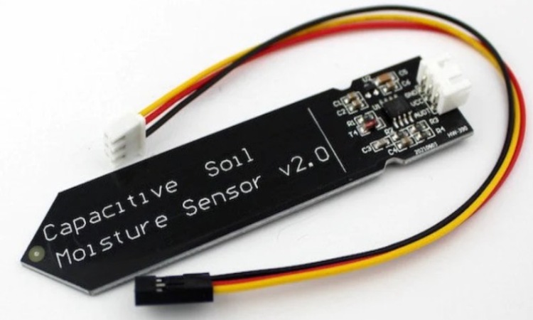
Capacitive soil Moisture Sensor
Capacitive soil Moisture Sensor
3.7 V Li-ion Battery
3.7 V Li-ion Battery
Capacitive Soil Moisture Sensor
This sensor is an analog capacitive soil moisture sensor that measures soil moisture levels through capacitive sensing. The sensor adjusts its capacitance based on the amount of water in the soil. You can translate this capacitance variation into a voltage level, ranging from a minimum of 1.2V to a maximum of 3.0V. One of the benefits of the Capacitive Soil Moisture Sensor is its construction from corrosion-resistant materials, ensuring a prolonged service life.
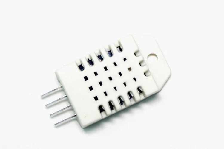
DHT22 Humidity Temperature Sensor
The DHT11 is a basic and very cheap sensor that measures both temperature and humidity. It uses a special sensor to find out how much humidity is in the air and a temperature sensor to measure the temperature. The sensor gives us this information in a digital way through a single wire. It's easy to use, but we need to be patient because it takes about 2 seconds to get new information. In our project, we'll use this sensor to tell us how hot and humid the air is.
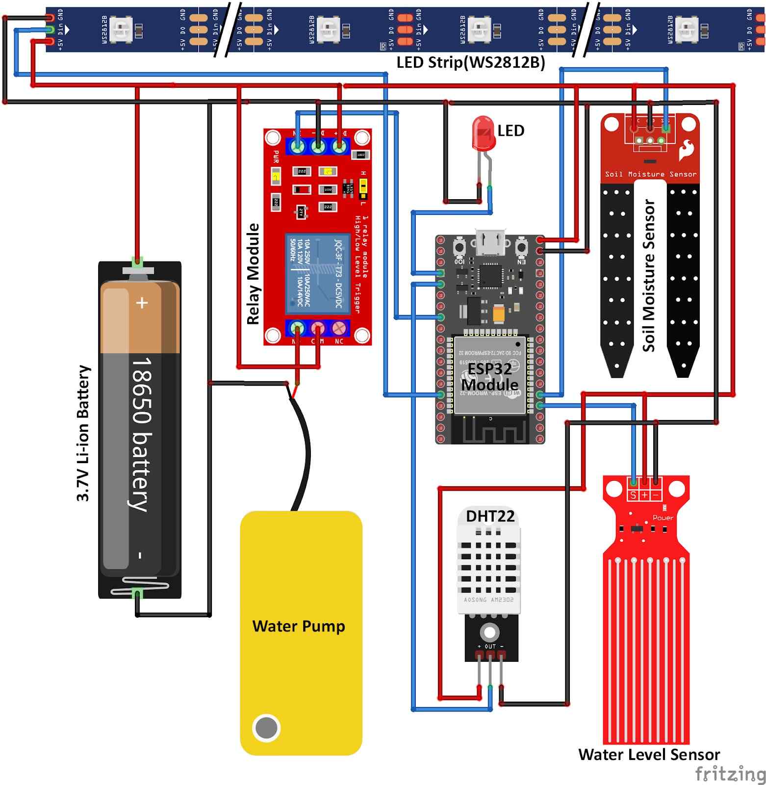
Circuit Diagram of the ESP32 Smart Irrigation System
Circuit diagram for this IoT Smart Irrigation System is given below.
Connect the soil moisture sensor to D35 pin of ESP32, water level sensor to D34 pin and DHT22 to D4 Pin. The motor connects to Relay. To control the relay, we use the D5 Pin of ESP32. Connect the RGB LED strip to the D21 pin of ESP32. You can power the Motor and Relay using the 3.7V from the Li-ion battery. The DHT22 Sensor, Capacitive Soil Moisture Sensor, and Water level sensor requires a 3.3V Supply only.
Now, we created the New Blynk Application.
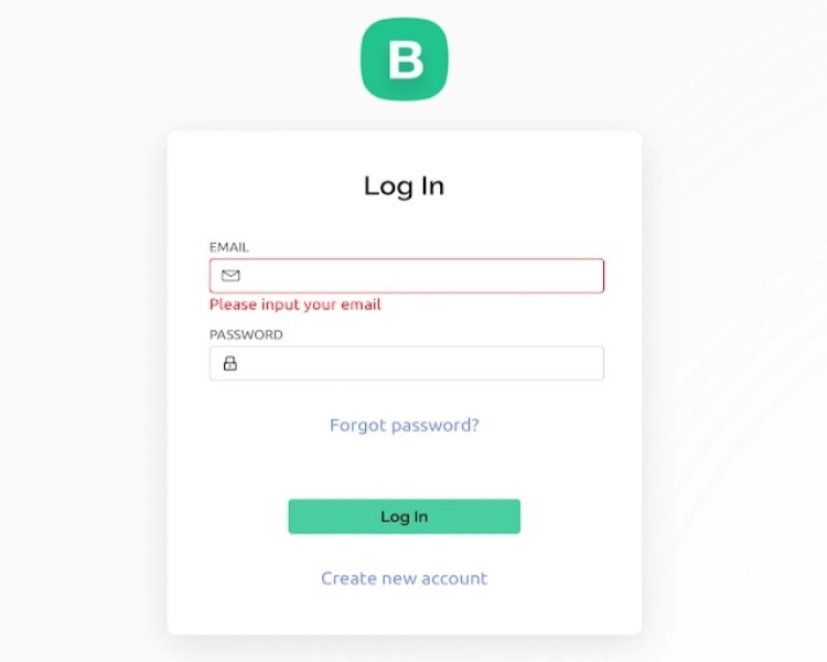
After creating the account, please visit https://blynk.io. Then enter the email id and password, and click on login. First you have to create New Template in the Blynk App.
For creating a New Template in Blynk App account, follow the following steps. Goto Developer Zone in the left side menu. Click on the My Template menu. Create a new template.
From the Widgets menu you can add the Button Widgets and Gauge Widgets to the interface. Then, name it as you like and select the virtual pin as V0. Next, change the values from 1 to 0 and change the mode as the switch for Gauge widgets change the input values from 0 to 100. Finally, customize these widgets as you like.
In device info you find your Template ID, Template Name, and AuthToken, copy and paste into the code.
ESP32 Smart Irrigation System Code Explanation
This code combinations of IoT, RGB LED Strip animation, and sensors like DHT22, soil moisture sensor and water level sensor, controlled and monitored through Blynk. The pump and Indication Led are controlled based on soil moisture and water level. Additionally, there are functions for changing color palettes and other visual effects of RGB LED Strip.
WiFi library — Download
WiFi library — Download
Blynk library — Download
Blynk library — Download
DHT library — Download
DHT library — Download
FastLED library — Download
FastLED library — Download
These lines define the Blynk template ID, template name, authentication token, and configure the serial output for Blynk.
This section includes necessary libraries (WiFi, Blynk, DHT, FastLED) and defines the authentication details and Wi-Fi credentials.
Configures LED matrix parameters, such as pin, brightness, type, order, and layout.
Configures the DHT sensor and defines pins for soil moisture, water level and LEDs.
Sets the thresholds for soil moisture, pump pins, and variables related to pump control and water level.
Initializes serial communication, output pins, Blynk connection, and LED matrix.
Functions triggered by Blynk app interactions, controlling pump, Mode (Automatic & Manual) and RGB LED strip.
If the system is in automatic mode (pumpMode == 0), it reads the soil moisture level using the soil moisture sensor. The sensor value is mapped to a range between 0 and 100, and the autoControlPump function is called to control the pump based on soil moisture.
Reads the water level from the water level sensor. If the water level is below a threshold (450), it sets the water level to 0. Otherwise, it maps the water level value to a range between 0 and 100.
Calls the controlLED function to control the LED based on the mapped soil moisture level. Then, it calls the readAndSendSensorData function to read temperature and humidity from the DHT sensor and send the data to the Blynk app. Additionally, it sends the water level to Blynk.
Testing of ESP32 Smart Irrigation Project
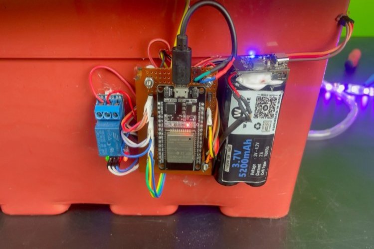
This water pump is designed to be fully submerged in water. The outlet pipe is strategically placed in a field for irrigation.
The soil moisture sensor is inserted into the soil, and similarly, the water level sensor is submerged into the water tank. Upon powering on the device and opening the Blynk App, the ESP32 automatically connects to your Wi-Fi, providing real-time data on Soil Moisture, Water Level, Air Humidity, and Air Temperature directly on the Blynk App.
In Automatic mode, if the soil moisture content decreases, the water pump activates automatically, irrigating the field until the desired moisture level is reached. Meanwhile, in Manual mode, you have the flexibility to control the pump manually, turning it on or off at your convenience. For a visual demonstration of its complete functionality, you can refer to the detailed working showcased in the video below.
Complete Project Code
how can i configuate the blynk
please my pump is still running, what's the problem
In reply to please my pump is still… by romanpalko
Make sure the connections to the relay module are correct. The positive of the motor should be connected to the normally open terminal. Also, check weather the soil moisture sensor is working properly or not.
Why did you choose to use ESP32 Board?
Can i do the same system using arduino uno r4 ?
In reply to Why did you choose to use… by surasalah
You can use Uno R4 WiFi. Modify the code accordingly.
Technologies used
Hardware components
- ESP32
- ESP8266
- Arduino
- DHT22
- Relay
- OLED
- NodeMCU
Software & tools
- Arduino IDE
- Blynk
- Firebase Console
- Node-RED
- MQTT Broker
Project demo video
What you get
- Working project / hardware kit, tested before delivery
- Complete source code with explanation
- Project demo and guidance for your viva
- Project report, PPT and IEEE paper support (on request)
Related IoT projects

DIY IoT Plant Watering System using Arduino
A remote plant-watering system that monitors soil moisture and lets you trigger a water pump from anywhere through the Blynk app, with LED-m...
View project
Build a smart mirror with an Arduino UNO Q
A wall-mounted smart mirror that shows the time, calendar, to-do list, room temperature/humidity and weather forecast behind a two-way glass...
View project
ESP32 Patient Health Monitor ECG SpO2 BPM Live Dashboard
Build a complete patient health monitoring system using ESP32 with AD8232 ECG sensor, MAX30102 pulse oximeter, BME280 and live web dashboard...
View project
IoT AC Energy Meter with PZEM-004T and ESP32 WebServer
Build an IoT-based AC energy meter using ESP32 and PZEM-004T to measure voltage, current, power, frequency and energy with live web dashboar...
View project